17/02/2026
Once
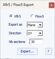
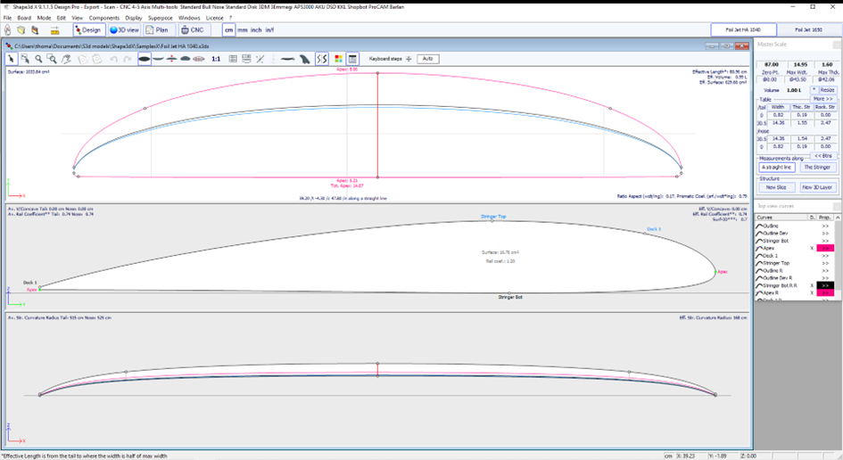
the foil has been designed in Shape3d, you can export it to Xfrl5 or Flow5 from
the menu File -> Xflr5/Flow5 export, Component -> Slices -> NACA
profile generator menu:
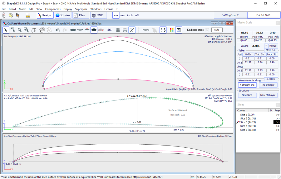
Note that
the foil must be designed as in the screenshot delow: with the leading edge to
the right, and the trailing edge to the left.
Xflr5 is
open source software that can be downloaded from https://www.xflr5.tech/xflr5.htm
The export consists of the defined number of
.dat profiles (30 here) and an xml file.
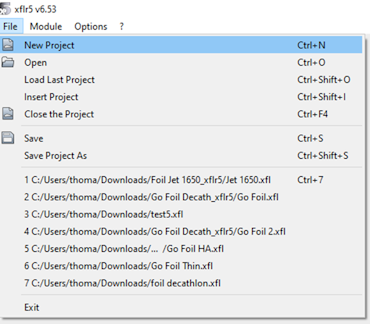
Open
Xflr5 and click on the File -> New Project menu:
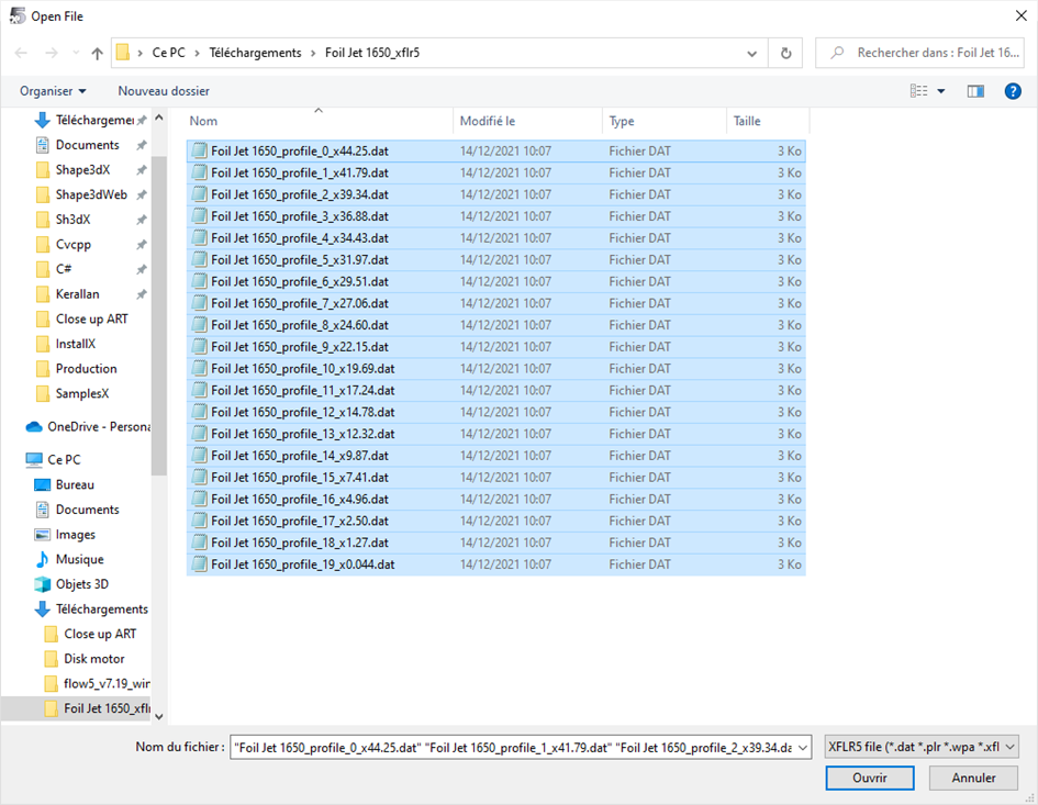
Then
File -> Open, and select all the .dat:
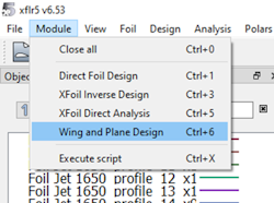
Then go to
the menu Module -> Wing and Plane Design:
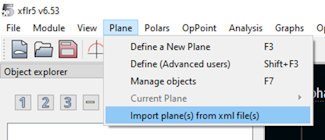
Then Plane
-> Import plane(s) from xml file(s):
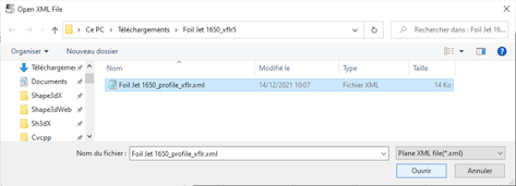
And select
the xml file exported by Shape3d:
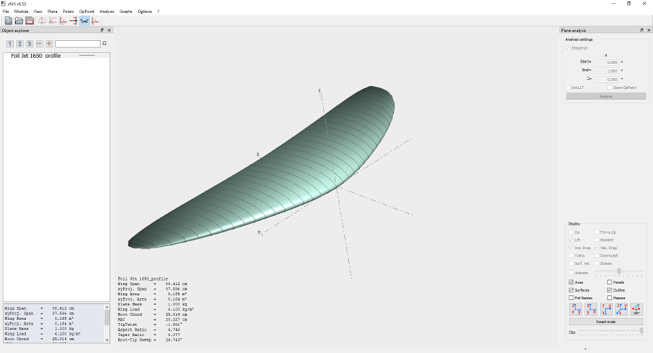
In 3D View
mode, we can check that the foil has been imported correctly:
We can then
directly launch a lift analysis from the Analysis -> Define an Analysis
menu:
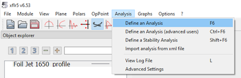
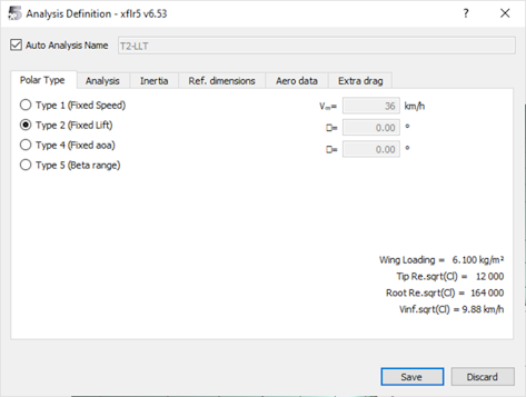
You can do
an analysis at a given speed (Type 1), or at a given lift (Type 2). The Type 2
analysis is very interesting to see how a foil will behave with a given user:
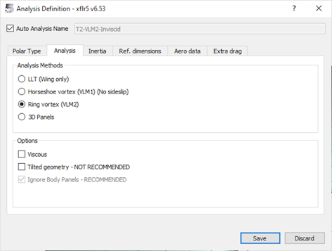
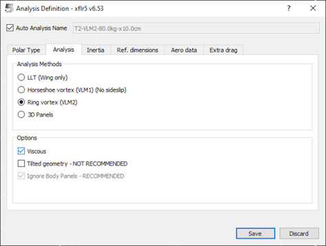
You must
then choose the method in the Analysis tab. Ring vortex works well. We're not
going to check Viscous just yet, which will allow us to get lift faster.
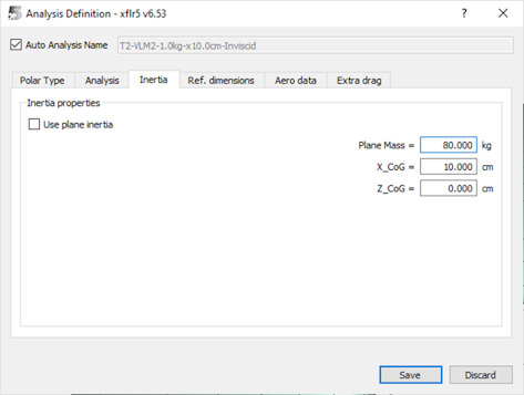
In the
Inertia tab we enter the weight of the rider + gear, 80kg for example:
Then in the
Aero data if tab, enter the water density 1000kg / m3 and its viscosity 1.3e-6
m² / s:
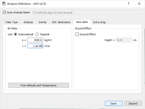
We click on
the Save button, then in Polar View mode we click on the Analyze button to
start the analysis:
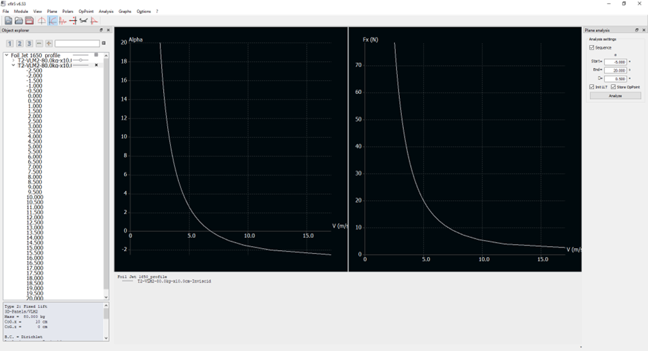
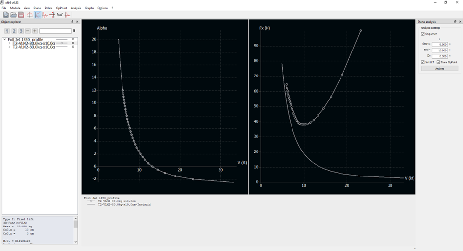
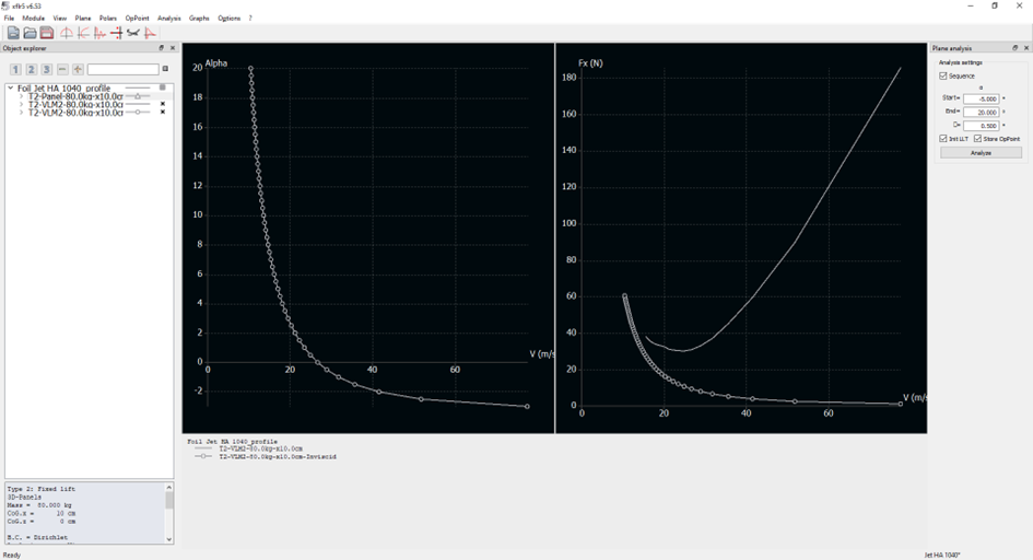
This
analysis calculates for each inclination of the foil (here between -5 ° and 20
°) the speed it takes for the foil to carry 80 kg (a lift of 784 N therefore).
You can also display the drag Fx for each speed (with the inclination that
corresponds to it).
Here we see
that for this low aspect 1650cm² foil (rough copy of the Naish Jet 1650), at 5
m/s (~ 10 kt) you need an inclination of 2 °. Below 6 kt it takes more than 12
°... We can deduce that we can start pumping around 6 kt, but that normal
navigation is only done from 10 kt roughly.
The drag Fx
is here only the residual drag due to the vortices, and we see that it is
greater the lower the speed and the large inclination. It only decreases as
speed increases, which is unrealistic as there is no viscous drag.
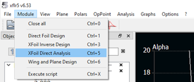
To add the
slimy drag it is a bit longer. You have to go to the menu Module -> XFoil
Direct Analysis:
Then in the
Analysis -> Batch Analysis menu:
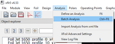
Then select
all the profiles, and launch the Type 1 analyzes between -5 ° and 20 °:
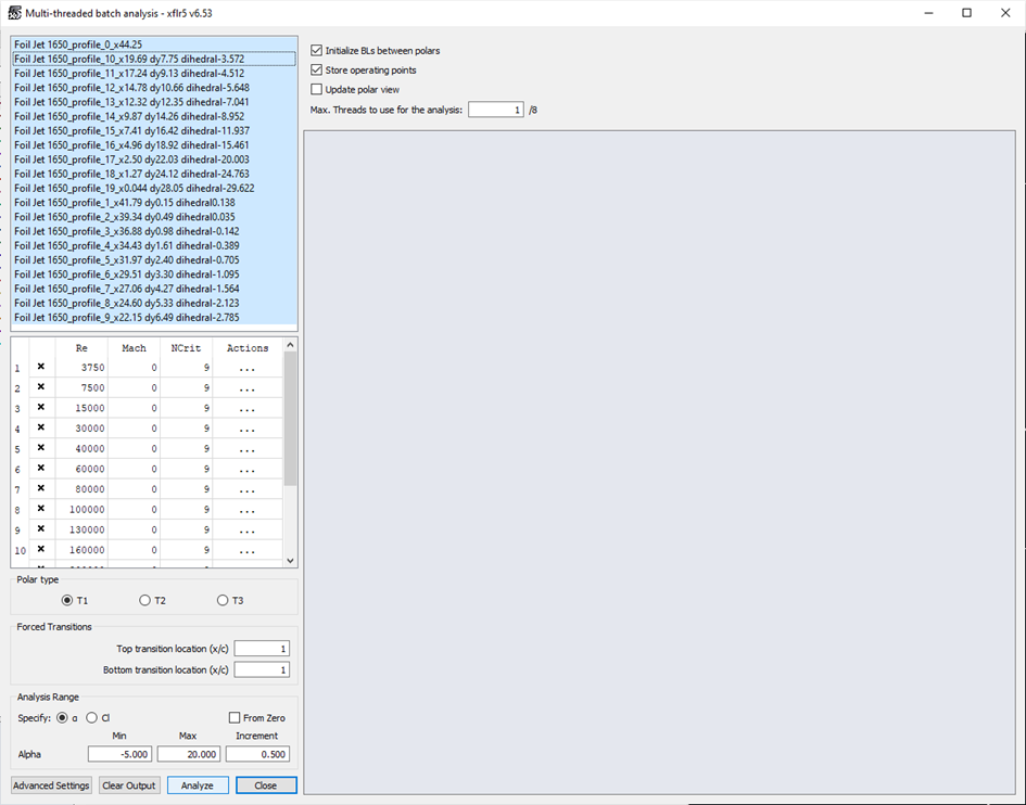
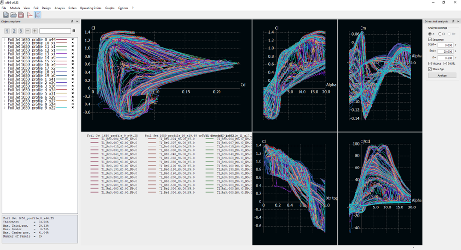
It takes
several minutes, and at the end of it, the polars for all angles and Reynolds
numbers between 4000 and 3e6 are displayed.
We can then
return to the Module -> Wind and Plane Design menu, and define a new
analysis, by checking the Viscous box this time:
We obtain a
lift identical to the previous analysis, but a higher drag which increases at
high speed. There is therefore a minimum drag for a given inclination and
speed:
There is
therefore an optimum range of use between 9 kt and 12 kt.
Note that
you can change the speed unit in the Options -> Preferences menu, but there
is a small bug that causes the display to always revert to m/s with a scale
that is not always good . You must then right click -> Current Graph ->
Define Grapgh Settings, then Reset Graph Scales.
We can
compare these results with a foil of 1040 cm² of higher aspect ratio (rough
copy of the Naish Jet HA 1040):
We can see
here that the bank at 10 kt is not 2 ° but 4 °. We descend to 2 ° around 12 kt.
The minimum drag is around 14 kt, and the optimum range between 12 kt and 16
kt.
These
results are not 100% reliable, but fairly true. We made a quantitative
comparison with the results obtained with OpenFoam (a large simulation
software, the analyzes are very long and require large computers) by Decathlon
and we were very close to the lift level for inclinations of up to 15 °. The
advantage here is that it takes less than 5 min in total to get an analysis.
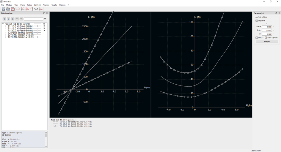
You can
also do Type 1 analyzes to obtain the optimum incline at a given speed
(10-15-20 kt here):
You can
also add a stabilizer: in Shape3d export it as a Wing, and then add it to the
plane you already created/
The same procedure
can be done to export your foil to Flow5, which is more advanced than Xflr5,
and which is now free as well:
https://flow5.tech/flow5.html
In Shape3d,
make sure you export your foil wing as a Plane:
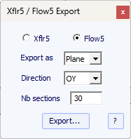
Then the
.dat profiles and an Xml file will be exported to the selected folder just as
for the Xflr5 export.
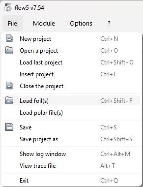
In Flow5,
create a new plane, and go to the menu File / Load foil(s) to load the .dat
profiles.
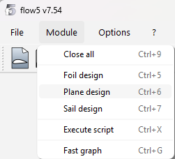
Then go to
the menu Module / Plane design:
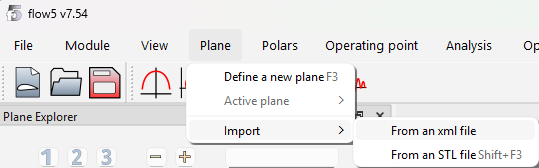
And then
Plane / Import / From an xml file:
You’ll see
the result of the importation straight away in 3D:
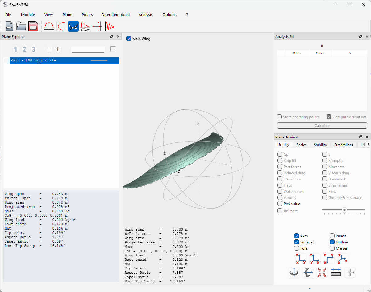
The analysis
procedure is then similar to what you do in Xflr5 but has more advanced
functions.