SHAPE3D X
User Manual
Version 9.1.3.4
01/06/2026
SHAPE3D X
User Manual
Version 9.1.3.4
01/06/2026
You can download the Shape3d installer (PC or Mac) at Download page. You need to Login first!
The Shape3d installer for PC is a .exe file like Sh3dX_9120.exe. It works Windows 7 to 11.
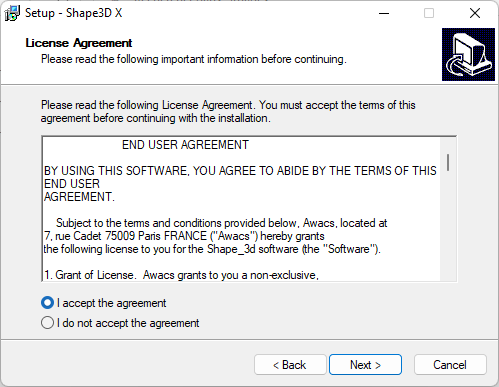
To start the installation double-click on the exe file. Then this window will pop up:

Click Next and then check I accept... to accept the user agreements.
Then keep clicking Next until you get the Finish button. You're done then!
If you get this error message it means that Shape3d is already open on your computer.
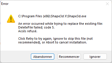
Close all the instances of Shape3d on your computer and then start again!
The Shape3d installer for Mac is a .dmg file like Sh3dX_9120.dmg.
Note that the different versions of Shape3d don't work on all OS versions!
For exemple for the OS Captain or Sierra you'll need version 9.1.0.2, the more recent versions won't work.
To start the installation double-click on the dmg file. Then this window will pop up:
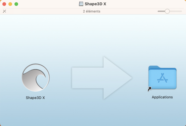
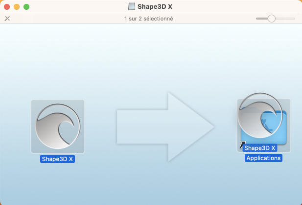
Drag the Shape3d logo and drop it on the Application folder.
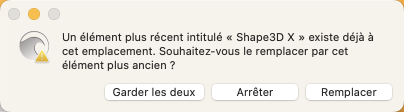
If Shape3d has been installed before a window will pop up to ask if you want to replace the previous version. Click Replace then.
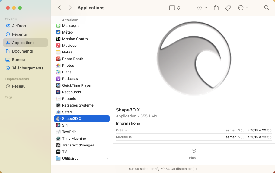
Once it's finished, go to the Applications folder and you'll see the Shape3d X appication. Double-click on it to launch Shape3d.
The first time you'll be asked if you realy want to open Shape3d X as it is a downloaded application. Click Open.
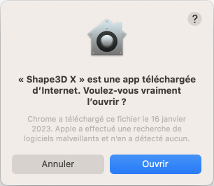
You can choose to keep the Shape3d X logo in the Dock to open Shape3d easily next time.
If your Mac doesn't allow you to install Shape3d then you need to check the "Privacy & Security" parameters in the "System Settings...":

In the panel "Allow applications downloaded from" you need to tick "App Store and identified developers":

If you can't find your files in the Shape3d File Selector or the file browser, then you also need to verify the parameters in "Privacy & Security"/"Files and Folders":

Shape3d X must have access to all your folders:

If you're experiencing repeated crashes of Shape3d you should also look at the "App Management" parameters and allow Shape3d X to update or delete other applications:

For any other problem with the installation of Shape3d X on your Mac check the FAQ: www.shape3d.com/FAQ.aspx
Note that the Mac installer has been build using Wine.
The first time you launch Shape3d Lite after installation, if Shape3d has access to the Internet, the following window will pop-up:
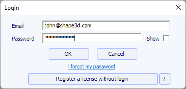
You'll need to use the same login (your email) and password you used when you created your account on our website.
Click on the OK button and you'll be all set!
If you don't have access to the Internet, you'll get the following window:
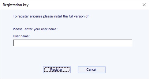
Enter a User Name, and let the Registration key blank. Then click on the Register button.
If you have Shape3d Lite installed, you need to uninstall it and install the full version instead!
You can download the full Shape3d installer (PC or Mac) at Download page. You need to Login first!
- If Shape3d has never been used on your computer, and if it has access to the Internet, the first time you open Shape3d you'll be asked to login. You'll need to use the same login (your email) and password you used when you created your account on our website:
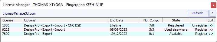
Once you're logged in the License Manager will open, showing the list of your valid licenses:

Just click on Activate >> to activate your license. That's it, you're all set!
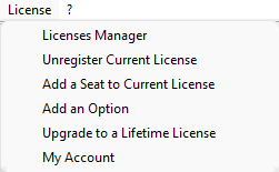
- If you installed Shape3d before without registering a license, the login window won't pop up. Then go to the menu License and click on the item License Manager.
Then you'll be asked to login and you can follow the instructions above.
- If you used a license earlier that has since expired, then at the opening of Shape3d you'll be asked to either Activate a license or Order another license, or Keep using the Lite version:

If you renewed your license on our website, or purchased another one, then press Activate to be redirected to the License Manager and activate it.
If not, press Order to be redirected to our website and renew your license, or purchased another one.
If Shape3d can't access the Internet, you'll need to follow the Offline registration procedure. The offline registration window will give you the Fingerprint of your computer:
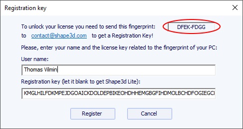
Select and copy the Fingerprint in the clipboard,
and send it to contact@shape3d.com.
We will send you back the unlock key by email as soon as possible.
Once you have receive it, enter your user name as given in the email, and the unlock key.
The key is pretty long, so do a copy-paste if possible to avoid mistakes. Make sure the fingerprint is still the same, as it can change in some circumstances.
If you want to use a license for which you have the reference, and the account email but not the login password, you can activate the license pressing the button Register a license without login in the Login window:
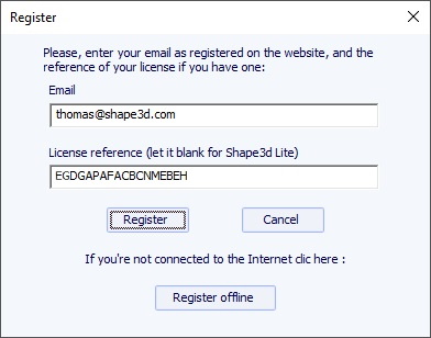
Enter the account email and the license reference and click on the "Register" button.
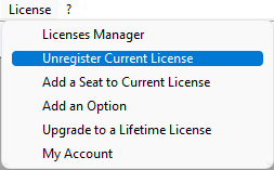
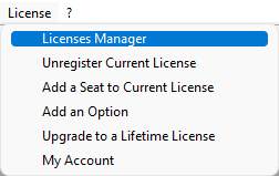
If you want to tranfert your Shape3d license to a new computer you'll have to unregister it from your actual computer first. For that, go to the menu License of Shape3d, and click Unregister Current License:
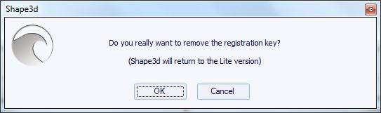
Shape3d will ask you to confirm that you want to remove the license.
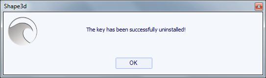
If you're connected to the Internet, this will also remove the computer fingerprint from our database, so you can register your license on another computer straight away. You'll see this confirmation window then:
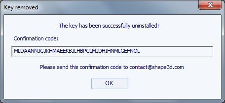
If you're not connected to the Internet, you'll see this window that contains a Confirmation Code. Send us this confirmation code at contact@shape3d.com so we'll know that you no longer use Shape3d on this computer and that you can register your license on another one:
Shape3d will then revert to Shape3d Lite.
Note that if you have several licenses registered on your computer and you only want to unregister one of them, you can do it from the License Manager.
Then, you can register your license on your new computer using the License Manager as explain above.
If you couldn't unregister your license from your old computer, you can still do it from your new computer,
provided Shape3d can access the Internet, and the old computer hasn't been used for the past 2 hours.
Open Shape3d on your new computer, go to the menu License and click on the item License Manager:
You'll need to login using the same login (your email) and password you used when you created your account on our website.
Once you're logged in the License Manager will open, showing the list of your valid licenses.
Click on Activate >> at the end of the line showing the license you want to register:
Since the license has already been registered on your old computer, you'll be asked if you want to remove the license from this other compter:
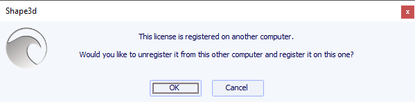
Press OK. This will automatically transfer the license to the new computer.

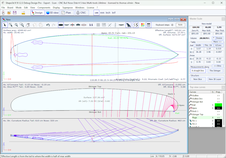
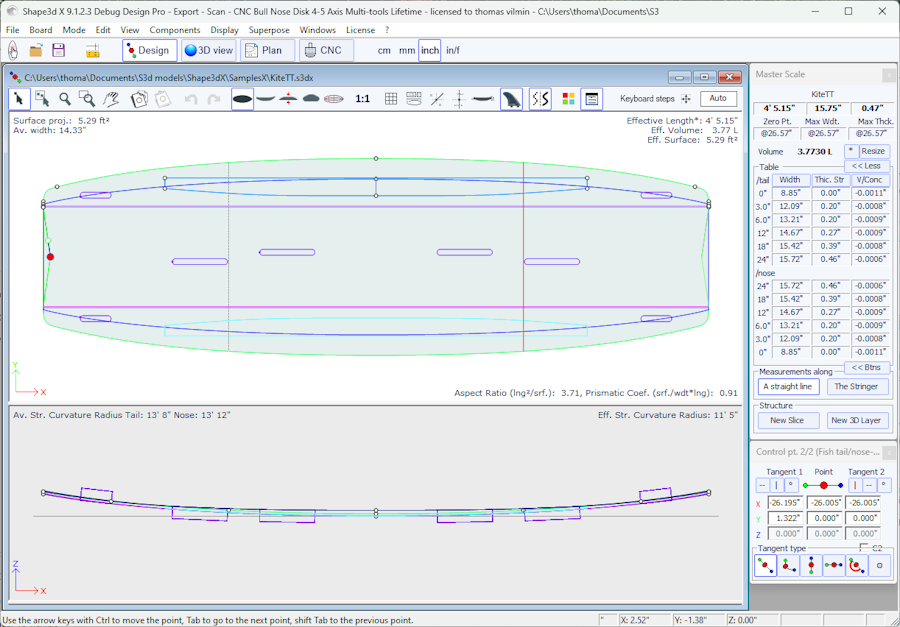
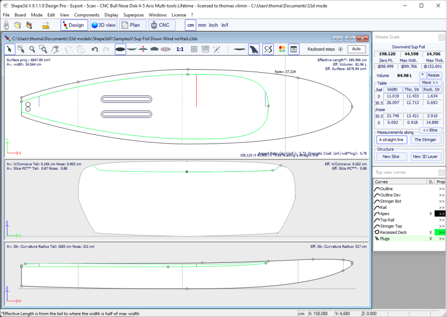
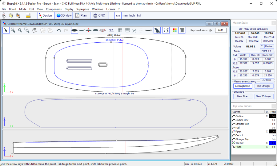
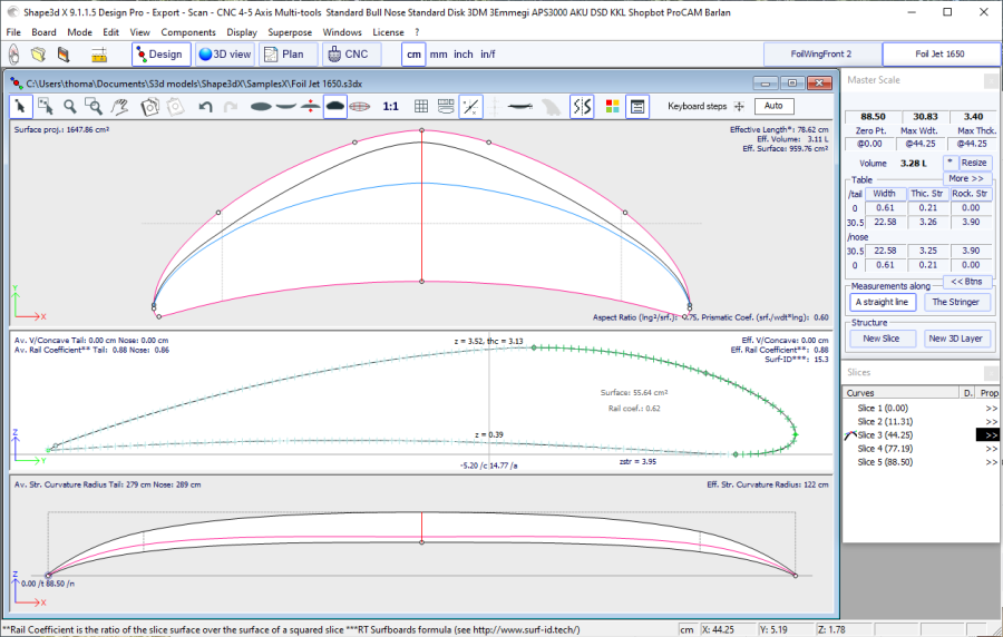
Shape3d presents four edition modes that can be selected in the general toolbar:
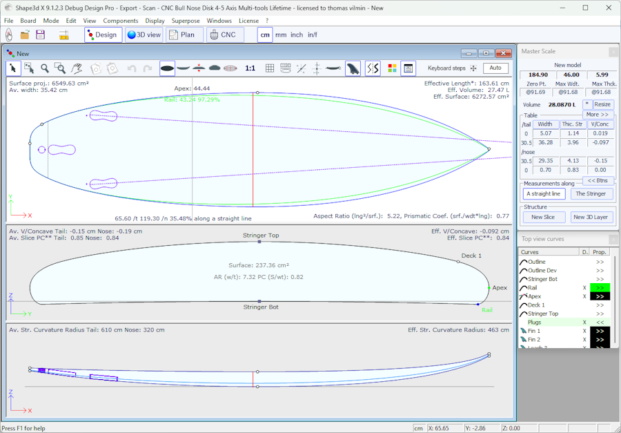
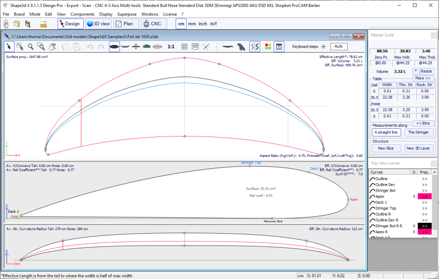
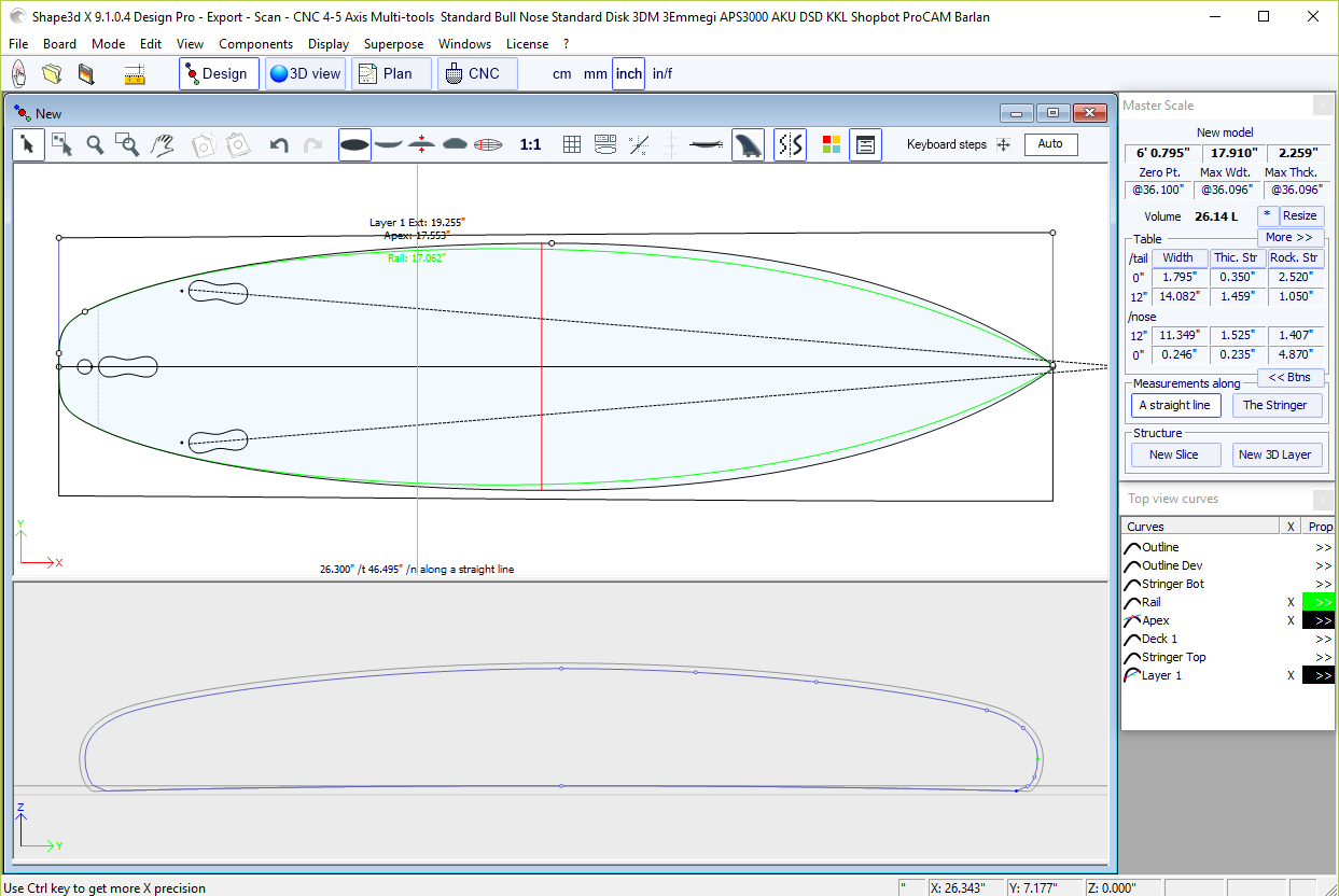
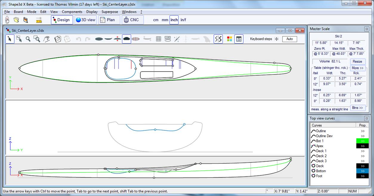
 The Design Mode presents three 2D views of the boards that can be
the outline, the profile, the thickness or the slices. In each view,
the curves can be modified through the control points. The measures
of the board are shown in the Master Scale box.
The Design Mode presents three 2D views of the boards that can be
the outline, the profile, the thickness or the slices. In each view,
the curves can be modified through the control points. The measures
of the board are shown in the Master Scale box.
You can always access this mode pressing Ctrl+1.
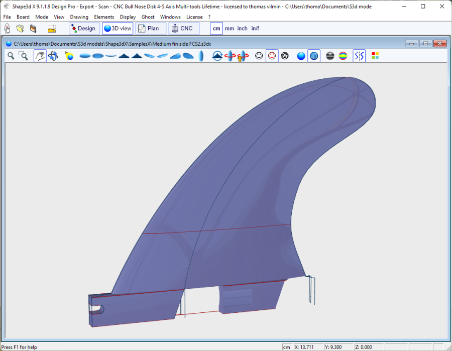
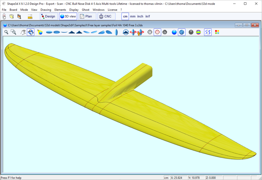
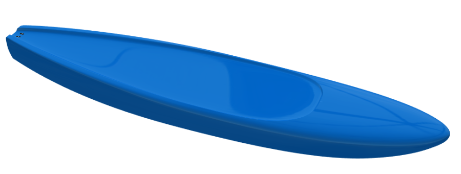
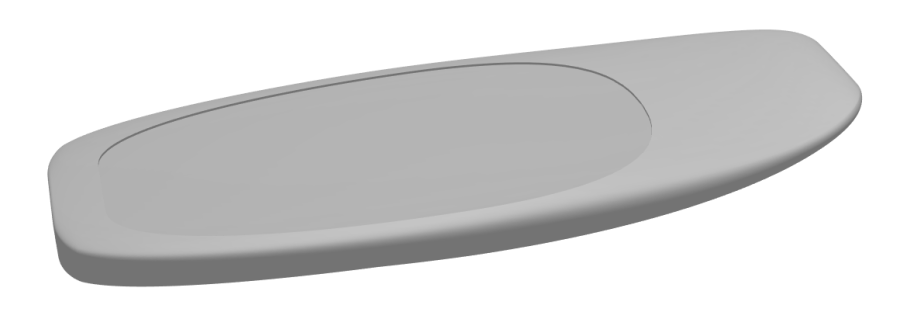
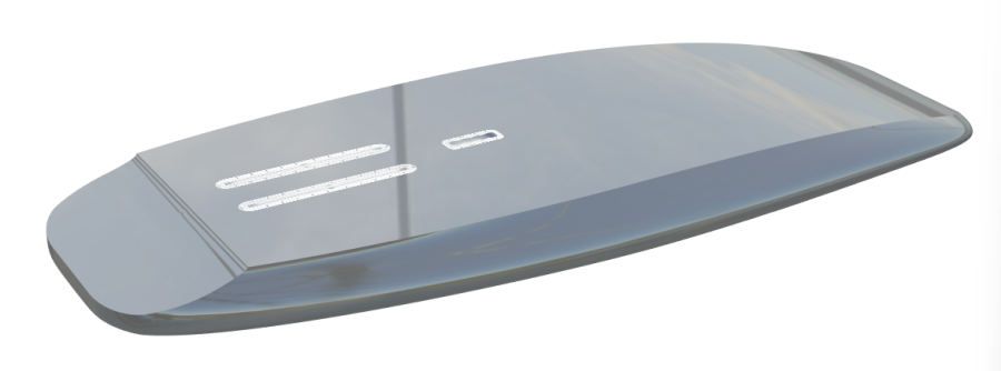
 The 3D Mode allows the visualization of the boards as a 3D object,
either with a solid rendering or a wired rendering.
The 3D Mode allows the visualization of the boards as a 3D object,
either with a solid rendering or a wired rendering.

Since version 9.1.3.0 you can open the 3D view in the Design mode!

The 3D view button
can either open the 3D in full screen
or open the 3D and keep the Design mode open at the same time,
depending on the option is selected in the Preferences.
You can press Shift to reverse.
You can always access this mode pressing Ctrl+2.
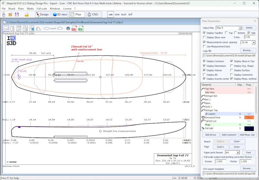
 The Plan Mode displays board charts with measurements, and
full scale printable view of the board.
The Plan Mode displays board charts with measurements, and
full scale printable view of the board.
You can always access this mode pressing Ctrl+3.
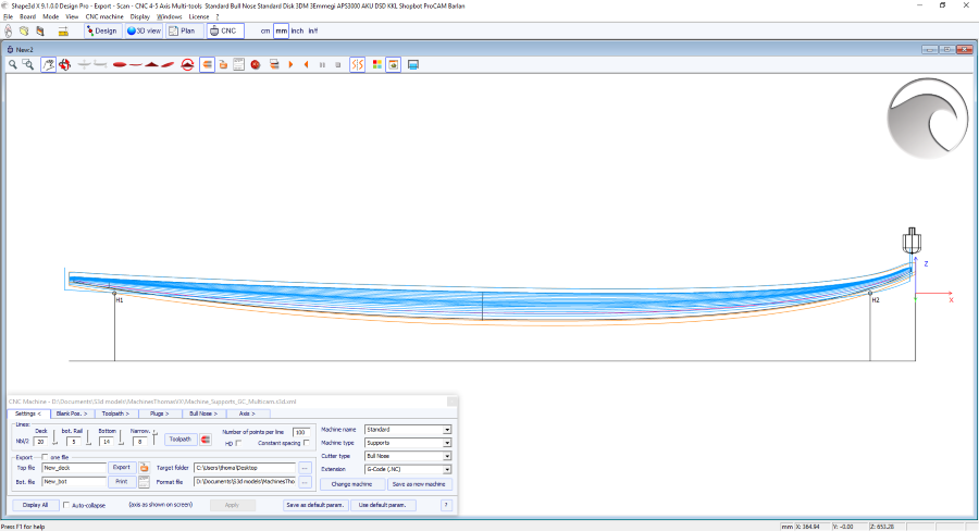
 The CNC Mode presents all the settings of the CNC machine,
and allows to compute, and visualize the cutting path.
The CNC Mode presents all the settings of the CNC machine,
and allows to compute, and visualize the cutting path.
You can always access this mode pressing Ctrl+4.
The general toolbar, which is accessible in each edition mode, also contains some general functions:
 This button opens a dialog box that allows creating a new board from
an existing model or from measurements.
This button opens a dialog box that allows creating a new board from
an existing model or from measurements.
 This button allows to open the file browser (or the File Selector) to load an existing file.
 Save the current model.
 Open the "Size & Parameters" dialog box that allows to change
the dimensions of the board, as well as other properties that will
be presented farther down.
Open the "Size & Parameters" dialog box that allows to change
the dimensions of the board, as well as other properties that will
be presented farther down.
 Select the measurements unit.
 Allows searching for functions in the menus.
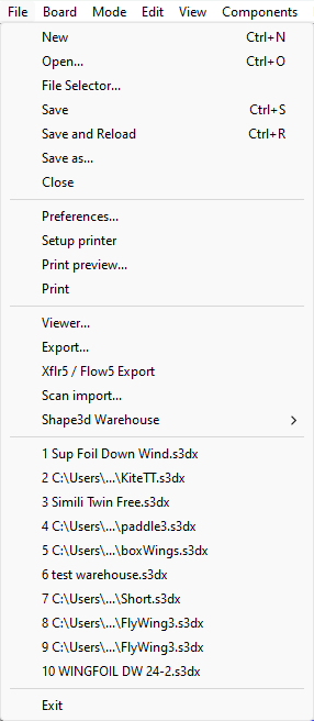
Go to the menu "File", then "New", or press the button "New" ![]() . The following window pops up.
. The following window pops up.
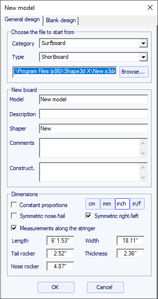
- The new model will start from a default file. You can define a different default file for each Category/Type of design (Surfboard/Shortboard, Longboard, Windsurf...). The default file when you install Shape3d is New.s3dx. Don't hesitate to change it to one of your own files!
- Enter the name of the model you are going to design, and your name as a shaper. Add any comments you want.
- Choose the dimensions' unit: centimeters, millimeters, inches or fractional inches.
- Check the box "symmetric nose/tail" for a twin-tip board. Uncheck "symmetric right/left" for asymmetric designs.
- Input length, width, thickness, and tail/nose rocker.
- Check the box "Stringer measurement" if these dimensions are measured along the stringer. Uncheck it if they are measured along a straight line.
- Press OK.
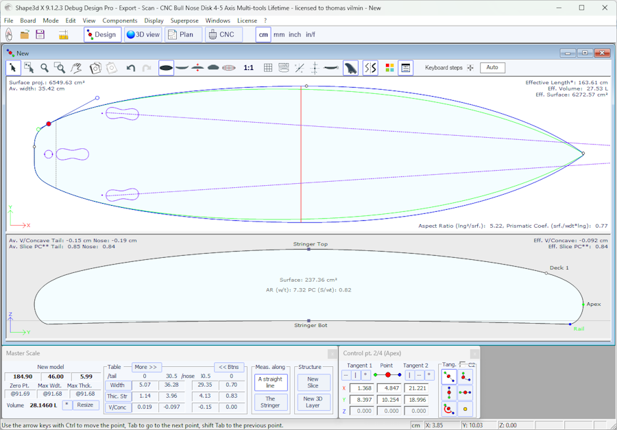
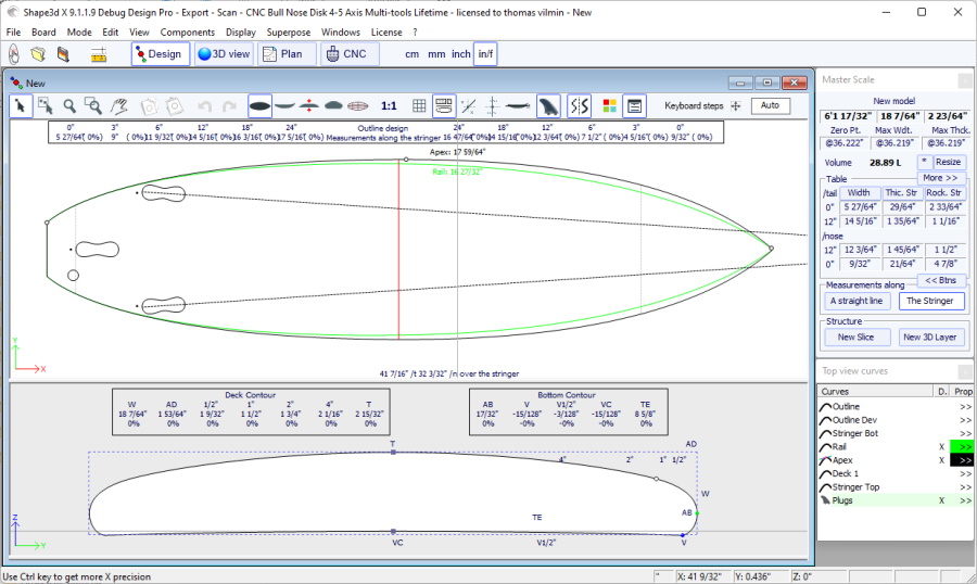
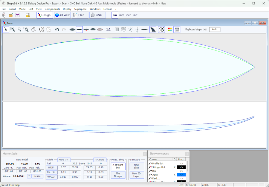
The starting model appears in the Design mode.
You can visualize three components of the board at the same time, choosing between Outline, Profile, Thickness, or Slices in the toolbar.
The dimensions of the board appear in the Master Scale box.
To modify the design of the curves, left click on the control points. The selected control point becomes red.
You can move the control points with the mouse, or with the arrows of the keyboard.
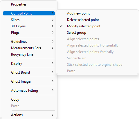
You can delete a control point pressing the button "Suppr" of the keyboard, or with a right click, selecting "Control point", "Delete".
You can also add a control point with a double left click at the position you want, or with a right click, selecting "Control point", "Add new point".
The properties of the selected control point are shown in the "Control point properties" box.
Five kind of tangents exist: continuous tangents ![]() , angular tangents
, angular tangents ![]() , vertical tangents
, vertical tangents ![]() , horizontal tangents
, horizontal tangents ![]() , and continuous tangents with
fixed angle
, and continuous tangents with
fixed angle ![]() .
.
Continuous tangents are usually used. The angular tangents are more appropriate for the rail point of the slices, the vertical tangents for the apex of the slices, and the horizontal ones for the widest point of the outline, the zero point of the bottom, or the highest point of the thickness.
When designing the slices, it is recommended to set the point type
of the rail point as ![]() , and the apex point as
, and the apex point as ![]() . They will then appear in blue and green
respectively.
. They will then appear in blue and green
respectively.
All the slices must have the same number of control points.
The position of the slices can be modified with a right click, selecting "Slices", "Move slice". It can also be changed with the mouse in the outline view.
You can add or delete a slice, in the same way.
You can visualize the "flow" of the slices maintaining a left click in the outline, profile or thickness view. The width, rocker or thickness appear at the same time, as well as the distance from the tail and from the nose.
To understand the idea behind the design of a board with shape3d, just think about the rule of thumb: the less points the smoothest. Similarly, the less slices the smoothest.
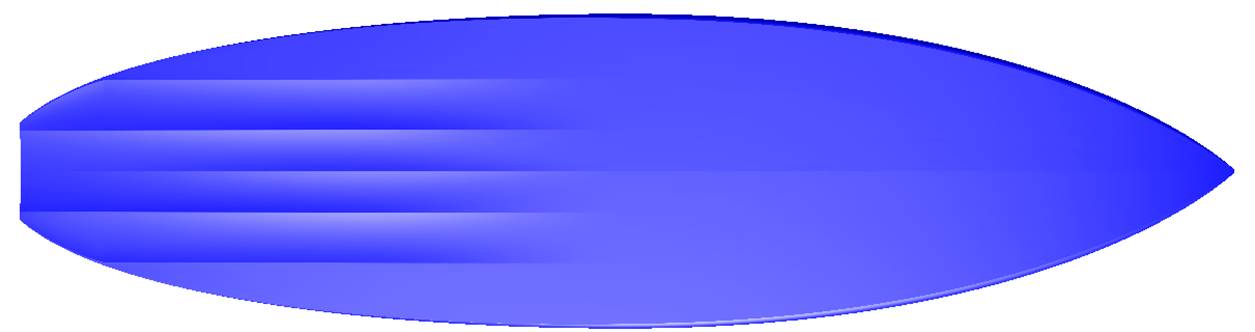
Visualize the result of your art in the 3D View mode.
Note that all these actions can be done with the fre Lite version of Shape3dX.
As if you would design a board from scratch, go to the menu "File",
then "New", or press the button "New" ![]() , and fill in the name and size
areas.
, and fill in the name and size
areas.
Then right click, select "Guidelines", "Guidelines Wizard":
The Guidelines Wizard window pops up. It allows filling in the measurements of the outline and of the profile:

You can choose to measure the dimensions of the board along the bottom stringer:

or along a straight line, checking the box "Straight line measurements":

Note that measuring the board "Along the stringer" is always less precise than "Along a straight line", as the x positions will depend on the design of bottom stringer curve.
Click on the button more if you want to place the guidelines at other positions than the default ones:

The positions of the guidelines along the length direction depend on the chosen unit: in centimeters, the guidelines are located at 5, 10, 20, 30 cm... from the tail and the nose. In inches, the guidelines are located at 1", 3", 6", 12... from the tail and the nose.
You don't need to fill in each position box.
The outline and the profile will be automatically adjusted on the guidelines if you check the box "Automatic fitting". Note that the Automatic Fitting is not always good enough!
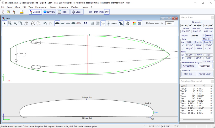
Press "OK" to see the board in the Design mode.
Note that the Guideline Wizard needs the Design option to be used, and the Automatic fitting needs the Pro option!
The guidelines appear as green crosses. Their list, with the positions, appears on the right hand side of the bottom of the screen.

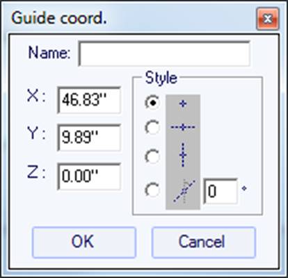
You can change their position with the mouse, or the keyboard, or with a right click in the "Guidelines" box, which will make the following window appear.
After changing the position of the guidelines, you can automatically fit the curves on the guidelines doing a right click on the selected curve.
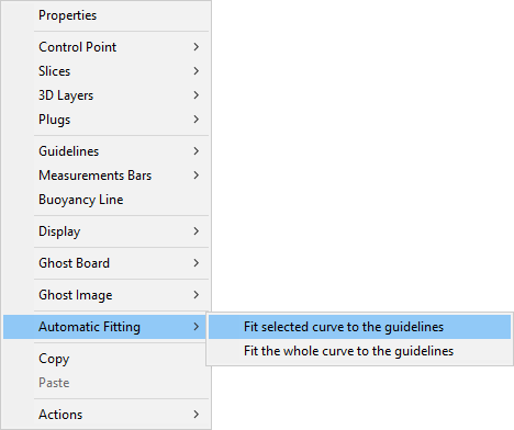
If you click on a curve section between two control points, you have the possibility to adjust only this selected part of the curve, choosing "Fit selected curve to the guidelines".
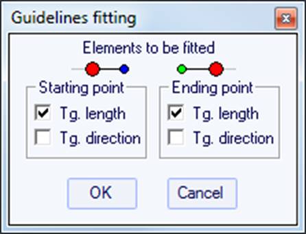
Then you have to choose if you want to adjust the length or the direction of each tangent, or both. And press OK.
You can also choose to adjust the whole curve, clicking on "Fit the whole curve to the guidelines".
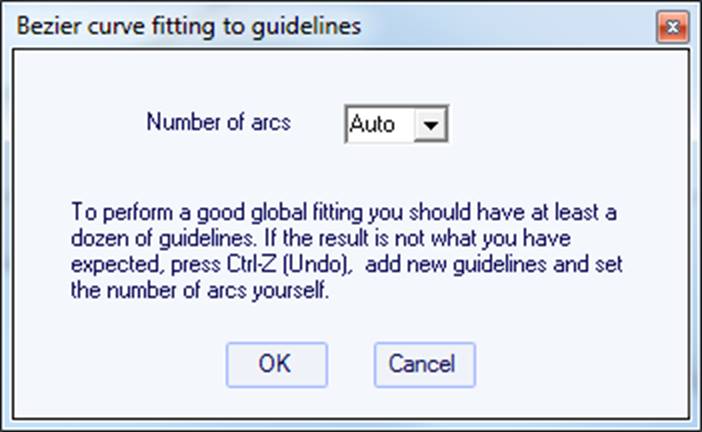
In this case you can choose the number of arcs (i.e. number of control points minus one) that will compose the whole curve. "Auto" will set it automatically, depending on the shape of the curve.
Once the design of the outline and profile is done, design the slices as explained in the chapter "Design a board from scratch".
Go to the menu "File", then "New", or press the button "New", and choose the tab "Blank design".
![]()
Set the rough measurements of the blank and press "OK". The blank will be automatically designed with square rails.
The smoothness of the curves is not guaranteed. You can modify the shape of the blank as shown in the chapter "Design a board from scratch".
Note that this can be done with the free Lite version of Shape3dx.
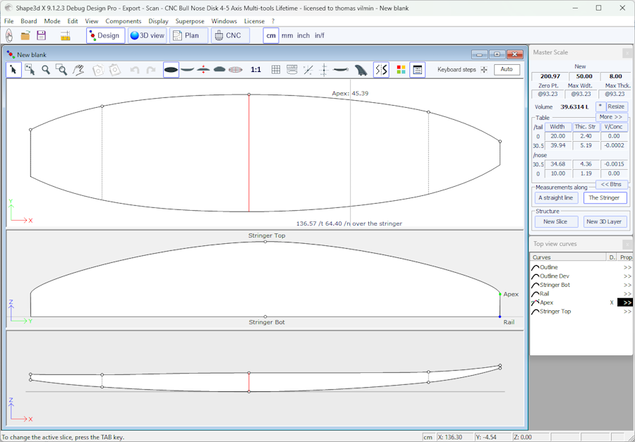
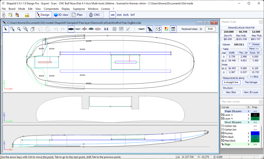
In the Design mode, the board is displayed projected in either the OXY, or OXZ or OYZ plan. The screen is splitted in up to 3 panels. The number of panels (1 to 3) can be changed in the menu Windows . The panels can be resized with the mouse.

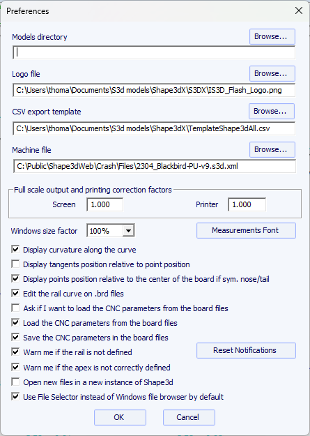
The "Preferences..." window can be opened from the menu File.
It contains general settings that concern the Design mode, but also the Plan and CNC modes.
The "New" window can be opened through the button ![]() of the toolbar, or through the menu File.
of the toolbar, or through the menu File.
- Choose the model to start from between the examples proposed in the Warehouse. You can define a different default file for each Category/Type of design (Surfboard/Shortboard, Longboard, Windsurf...).
- Enter the name of the model you are going to design, and your name as a shaper. Add any comments you want.
- Choose the dimensions unit: centimeters, millimeters, inches or fractional inches.
- Check "Constrain proportions" if you want to keep the same ratio Length/Width/Thickness/Rocker... as the starting model.
- Check the box "Stringer measurement" if these dimensions are measured along the stringer. Uncheck it if they are measured along a straight line.
- Check the box "Symmetric nose/tail" for a twin-tip board.
- Check the box "Symmetric right/left" for a regular board. Uncheck this option for an asymmetrical board.
- Input length, width, thickness, and tail/nose rocker.
- You can set the thickness of the sandwich if the board is designed to be built with the sandwich technology.
- Press OK.
The starting model appears in the Design mode.
![]()
Set the rough measurements of the blank and press "OK". The blank will be automatically designed with square rails.
The "File Selector" window can be opened through the menu File, or from the button Open
![]() of the toolbar.
Note that the first time you'll click on the Open button you'll be asked if you want to use the File Selector or the Windows file browser to open files.
This choice can be modified later on in the Preferences (menu File).
of the toolbar.
Note that the first time you'll click on the Open button you'll be asked if you want to use the File Selector or the Windows file browser to open files.
This choice can be modified later on in the Preferences (menu File).
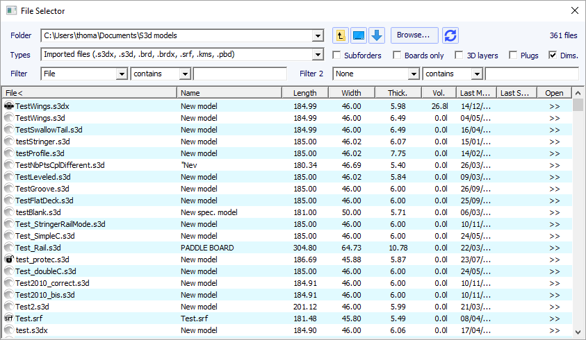
The File Selector shows the list of files of a selected folder, just like the the Windows file browser. It also provides a preview of the Shape3d files the same way:
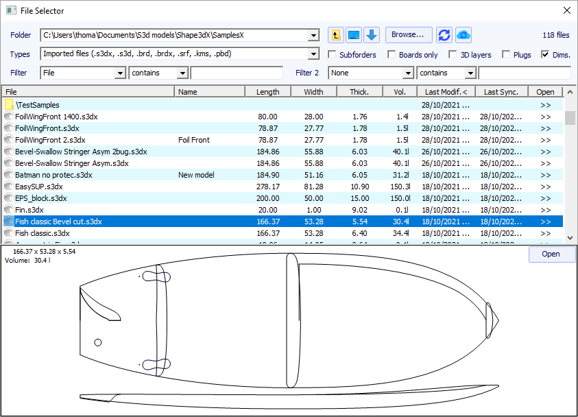
But in addition it gives you the dimensions of all loaded files, and allows you sorting and filtering the files by name, length, width...
and also category, type, rider profile...
It also has a contextual menu that allows Renaming, Deleting or Moving one or several files.
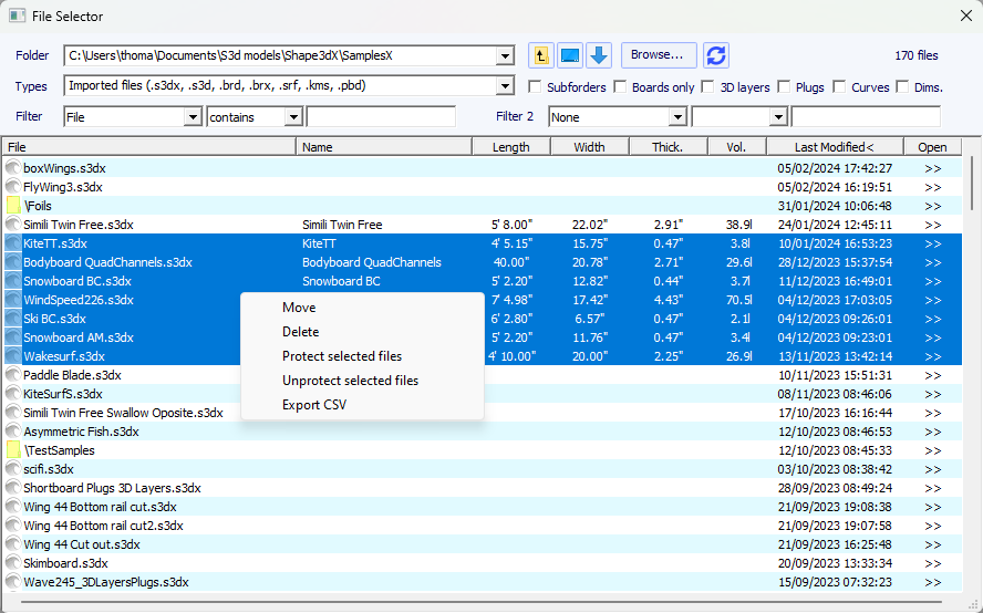
You can also Protect or Unprotect the selected files or all the files of the folder.
And you can do a CSV export of the dimensions and properties of the selected files.
Note that you need a Design Pro license to protect a list of files, and export the dimensions in the CSV format.
The "Size and parameters" window can be opened through the button ![]() of toolbar, or through the menu Board->Properties.
of toolbar, or through the menu Board->Properties.
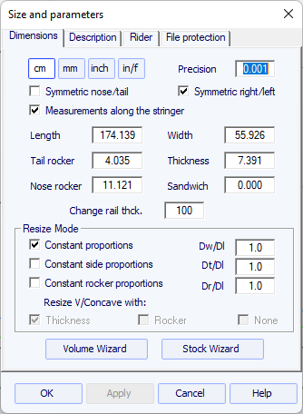
In the "Dimensions" tab you can change the measurements "Unit", and the "Precision" of the displayed measurements:
from 0.1 to 0.00001 (1 to 1/64" for fractional inches).
You can also change the symmetry properties of your design: "Symmetric nose/tail" and "Symmetric right/left".
And you can choose to display the length measurements "Along the stringer"
(which means that we measure the developped length along the bottom stringer curve of the board)
instead of Along a straight horizontal line. Note that the lengths are larger if measured "Along the stringer" mode!
The "Dimensions" tab allows Resizing your design. There are several resizing modes:
- The "Constant proportions" mode will modify the width, thickness and rocker proportionaly to the length.
- The "Constant side proportions" mode will only modify the thickness and rocker proportionaly to the length.
- The "Constant Z proportions" mode will only modify the rocker proportionaly to the thickness.
- And the "Constant rocker proportions" mode will only modify the rocker proportionaly to the length.
Note that in the "Constant rocker prop." mode you can choose to resize the V/Concave proportionaly to the thickness, or to the rocker,
or keep it constant while resizing the board (None, which was the default value before version 9.1.1.1).
These resizing modes can be parameterized with custom proportion coefficients between rocker and length variations (Dr/Dl), width and length variations (Dw/Dl),
and thickness and length variations (Dt/Dl).
The "Dimensions" tab also gives the possibility the increase or lower the "Rail thickness"
(change the rail thickness the 50% to make the rails half thinner, change it to 200% to make it twice thicker).
The "Sandwich" field can be used to remove a constant thickness on the whole board for sandwich construction.
The sandwich thickness removed on the slices is displayed in the Design mode, and it will be taken into account for the cut in the CNC mode
(the sandwich thickness can be changed in the CNC mode).
On the other hand, it is not taken into account for the 3D exports in the STL, DXF or IGES formats!
Note that the resizing can be done with the free Lite version of Shape3dx.
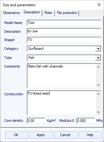
The "Description" allows you naming the design and adding descriptions.
You can select the Category and the Type of the design, which can be used to sort your files in the File Selector later on.
You can also define the density of the core, which will allow computing the final weight of the board.
And the Elastic Modulus, which will allow computing the stiffness of the board.
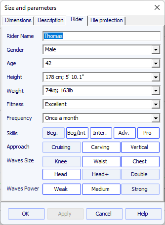
The "Rider" tab allows you registering the profile of the user of your design. These informations as well can be used to sort your files in the File Selector later on.
The files produced by Shape3d can be encrypted, to prevent other Shape3d users from reading, copying and/or cutting your boards.
The protection system can either use your License Name (the file is protected against anyone whose license name differs from yours) and/or a Password (other users will need your password to unlock the protection).
- Checking the box "No Modifications" prevents from the modification and copy of your model.
- If the box "Resize Only" is checked, then the model can only be resized from the Size and parameters window. The outline, profile and slices can't be modified by someone else than the file owner.
- Check the box "Cutting Path Only" to hide the board dimensions and cross sections. That's an additional protection to prevent any copy using the measurements given by Shape3d.
- Checking the box "No Cutting Path" blocks the export of cutting path. This level of protection can be set for all cutting centers except one. Select the cutting center in the drop down list then.
- Checking the box "No Reading after" will make the file impossible to open after the chosen date.
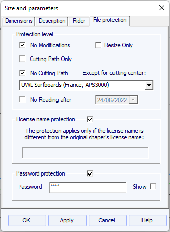
Note that the file protection needs the Design option to be used. Protected files can't be open with the Lite version of Shape3dX.
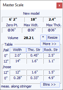
The "Master Scale" window  provides the general information on the board:
The name, and the volume, length, width, thickness of the model. It also gives the tail and nose rocker, the position of the zero point, and the measurements at 0 and 12" (or 0 and 30 cm) from the tail and the nose.
Press "Resize" to change the general dimensions of the board.
The "*" button opens the Volume Wizard window that allows adjusting a dimension to get the desired volume.

One can also visualize more measurements, clicking on "More >>".
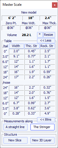
Note that measurement columns can be organized the way you want. And you can choose the display either the Width, the Stringer Rocker (center point of the bottom), the Profile Rocker (lowest point of the bottom), the Stringer Thickness (thickness at the center of the board), the Profile Thickness (thickness between lowest and highest points), or the depth of the V or Concave of the bottom of the board.
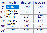
You can choose to edit the dimensions taken along a straight line or along the stringer line, pressing the button "A Straight Line " or "The Stringer".
- Measurements along a straight line give width and height measurements that are taken at a defined distance straight from the tail.
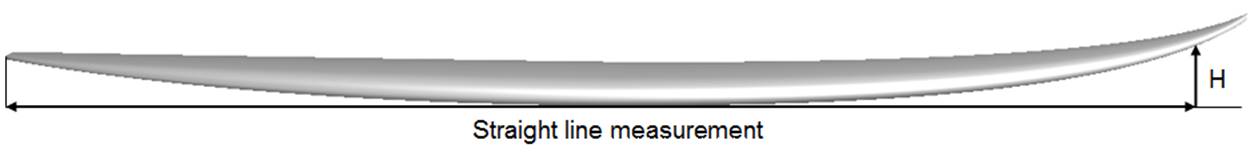
- Measurements along the stringer give width and height measurements taken at a defined distance along the curve of the bottom stringer from the tail.
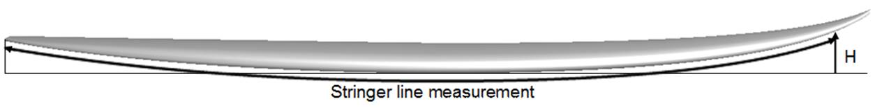
Note that 12" from the tail along a straight line is farther from the tail than 12" from the tail along the stringer, so it will give a larger width and smaller rocker. And 12" from the nose along a straight line is farther from the nose than 12" from the nose along the stringer.
You can also add a slice or a 3D layer.
The "Smart Functions"  allows doing classic actions quickly and easily:
For exemple you can "Set the Width at" any X position along the board.

It will acurately modify the Outline or Apex curve of the board to get the right measurement at the X position you chose.
The functions are:
- Set the Width at the X position you define.
- Set the Thickness at the X position you define.
- Set the Rocker at the X position you define.
- Set the V/Conc. at allows fixing the depth of the concave or the V at a given X position, and choose between a V, Concave or Double concave:

- Set the Rail at allows changing the shape of the slices, to make the rail more Boxy for exemple, with an edge (or tuck) from soft to square, and fixe the height of the apex from 50/50 to 80/20:


- Set the Tail shape allows changing the shape of the tail, you can choose between Square, Squash, Round, Round Pin, Pin, Diamond, Wings, Swallow, Fish, Moon, Bat, and set the length of the Swallow tail for exemple. Swallow, Fish, Moon and Bat tails will be designed using 3D layers, so a Design Pro license is needed.


- Set the Nose shape allows changing the shape of the nose.
- Add Fin plugs allows choosing between fins configurations Single, Twin, Thruster, 2+1, Quad, Twinzers, Combo, 4+1,
Foil tracks, and select the plug system. A Design license is needed to use this function.

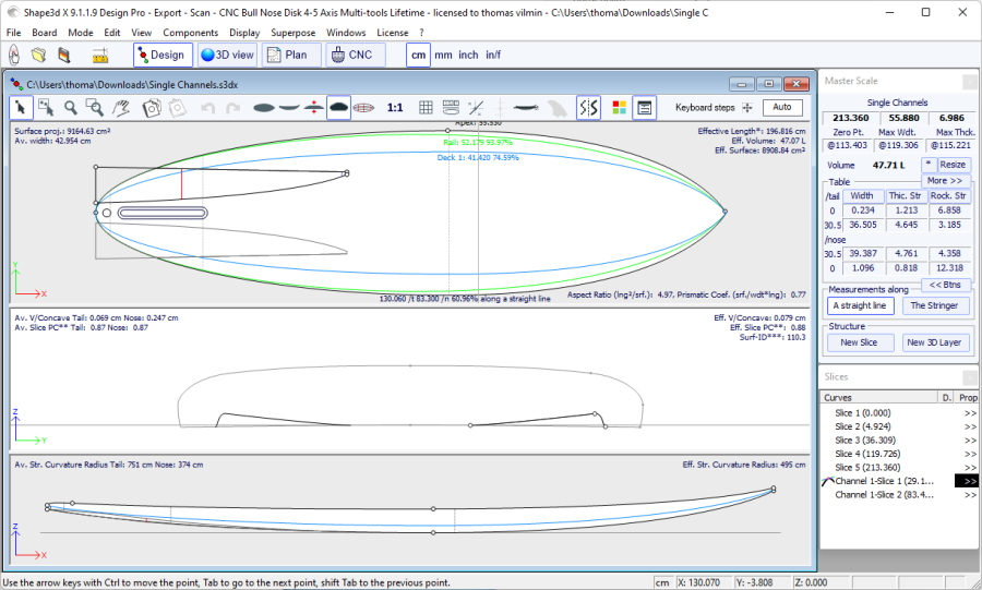
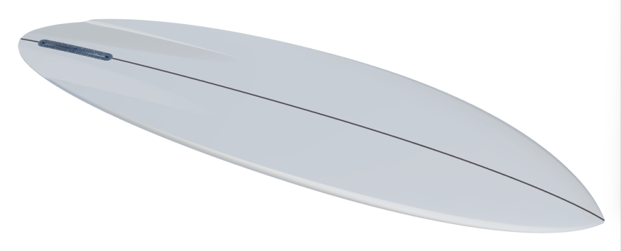
- Add Channels allows adding 2 Channels, 4 Channels, 6 Channels (straight, tilted ou curved), Venturi Channels, Belly Channels, or Deck Rail Channels, and set their length and depth. The channels will be designed using 3D layers, so a Design Pro license is needed.


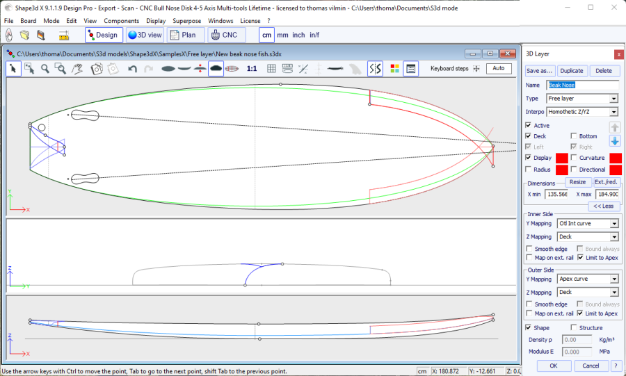
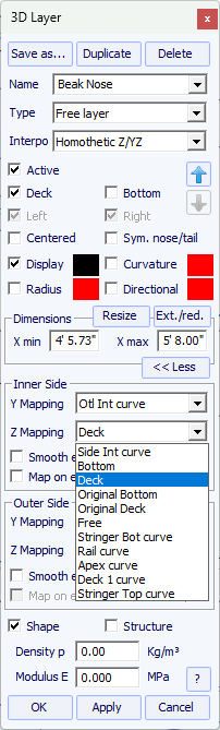
- Add Spoon concave allows adding a spoon concave 3D layer at the nose, and set its length and depth. - Add Recessed deck allows adding a recessed deck 3D layer, and set its length and depth. - Add Beak nose allows adding a beak nose 3D layer, over the length you set.
You need a Design license to use the Smart functions, and a Design Pro license for those that use 3D layers.
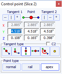
The properties of a selected control point are shown in the " Control point properties " box.
The position of the control point and its tangents can be changed manually. The modifications you enter will be taken into account if you change the cell or click Enter.

The "Rel" check box allows displaying the position relatively to another control point (from the same curve or from another curve). The "Fix." check box will fix the point to the selected control point so that the relative position doesn't change when it's displaced.
Five kind of tangents exist: continuous tangents ![]() , angular tangents
, angular tangents ![]() , vertical tangents
, vertical tangents ![]() , horizontal tangents
, horizontal tangents ![]() , continuous tangents with
fixed angle
, continuous tangents with
fixed angle ![]() , and passive point with no
tangents
, and passive point with no
tangents ![]() .
.
The "C2" option forces the curvature continuity on both sides of the tangent.
Continuous tangents are usually used. The angular tangents are more appropriate for the rail point of the slices, the vertical tangents for the apex of the slices, and the horizontal ones for the widest point of the outline, the zero point of the bottom, or the highest point of the thickness.
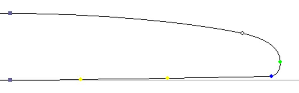
When designing the slices, it is recommended to set the point type
of the rail point as ![]() , and the apex point as
, and the apex point as ![]() . They will then appear in blue and green
respectively.
. They will then appear in blue and green
respectively.
All the slices of a board must have the same number of control
points. This can be annoying some time if it forces you to add
un-useful control points to a slice. In this case you can set the
point as passive ![]() . Then the control point will
be like a dead point and you won't have to set its tangents... The
passives points appear in yellow, and they have no tangents.
. Then the control point will
be like a dead point and you won't have to set its tangents... The
passives points appear in yellow, and they have no tangents.
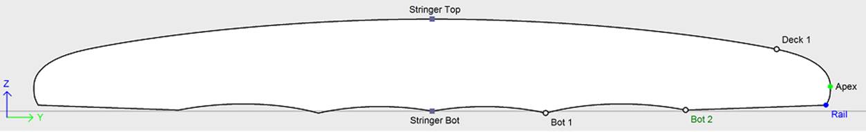
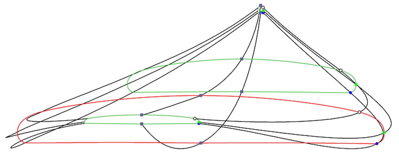
As we said earlier, all the slices of a board have the same number of control points. And the curves joining these points define the whole shape of the board.
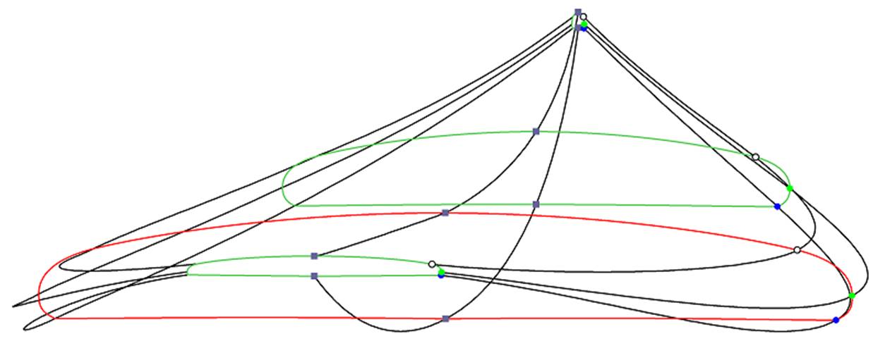
The control points of the slices are named automatically.
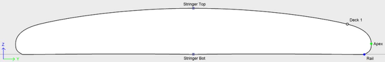
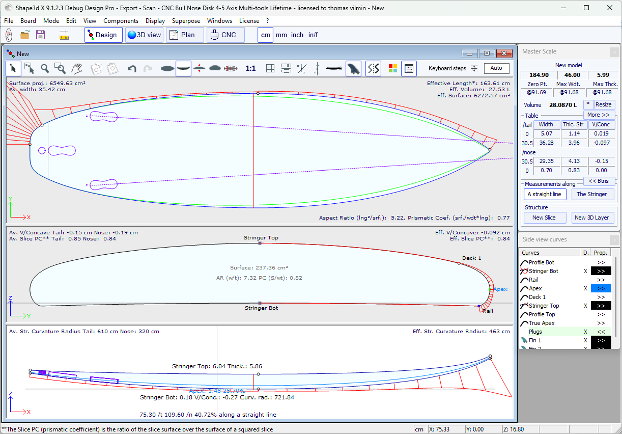
The curves that correspond to each of these points can be displayed both on the Top view panel and the Side view panel. When one of these panels is selected the list of the curves appears on the side:
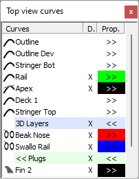
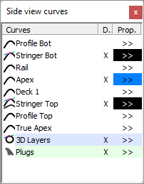
To display the properties of a curve, click on >> or double-click on its line.
The name of each curve can be modified. You can also select another curve from the drop-down list.
Each curve can be displayed or not in a different color. The
Curvature, Curvature Radius, and Directional Curvature Radius (same
as SurfCAD) can also be displayed in other colors.
If the option "Display curvature along the curve" is selected in the Preferences window (see menu File),
the curvature curves are displayed perpendicularly to the original curves.
In comparison, if this option is not selected, the curvatures are drawn along the X axis.
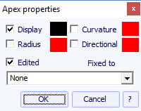
One of the most important new feature of Shape3d X is that each
curve (except the Developed Outline and the True Apex) can be Edited
or not in the Top and/or the Side view. If a curve is Edited ![]() , it means that the user can modify the curves moving
the control points and tangents. If a curve is Not Edited
, it means that the user can modify the curves moving
the control points and tangents. If a curve is Not Edited ![]() , it means that the curve is computed by Shape3d.
, it means that the curve is computed by Shape3d.
Note that you can edit or un-edit a curve if you right-click on it in the curves list.
The Edited curves can be set Fixed to another edited curve ![]() . This means that the relative distance between the
two curves will stay constant when the second curve is modified. For
example one can set the Deck Stringer line Fixed to the Bottom
Stringer line, so that the stringer thickness doesn't change when
the Bottom Stringer line is modified. This thickness can be
displayed in the Thickness View.
. This means that the relative distance between the
two curves will stay constant when the second curve is modified. For
example one can set the Deck Stringer line Fixed to the Bottom
Stringer line, so that the stringer thickness doesn't change when
the Bottom Stringer line is modified. This thickness can be
displayed in the Thickness View.
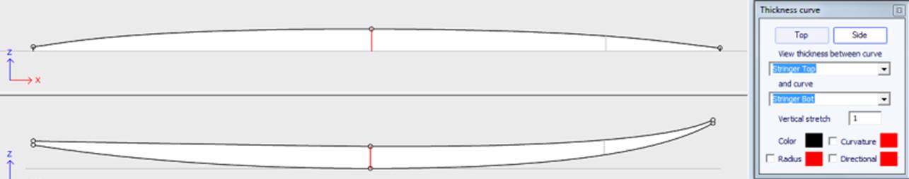
In the Thickness View, if the curve displayed corresponds to the thickness between a curve that is fixed to another one and this other curve, the control points appear and the curve can be modified. In this view the curvatures can be displayed, and the colors changed. Also the curve can be stretched vertically if it's too flat to be seen correctly.
When the Slices view is active, the list of curves is replaced by the list of slices.
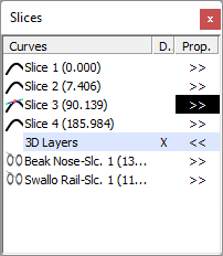
The slices are listed with their positions, which allows avoiding getting two slices at the same place.
Click on a line to edit the corresponding slice on the slices view. You can click in the Diplay (D.) column to display multiple slices. The diplayed slices (in addition to the edited slice) have a X in the D. column.
If you double click on a line, or click on >>, the slices properties window pops up.
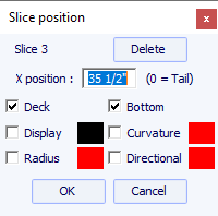
In this window you can change the slice position.
You can change its color and diplay or hide it.
You can also display the curvature, the curvature radius and the
directional curvature radius of the slice. And you can delete the
slice.
You can also select another slicte in the drop-down list.
Since version 9.1.0.4 the slices can be defined on the Deck only or Bottom only. This feature allows modifying the bottom or deck of the board without risking to decrease the smoothness of the board on the other side.
You can also save the slice in a separated s3dx file. And you can load the slice from an s3dx file that contains a slice or from a board file.
One of the most important new feature of Shape3d X is that each
curve (except the Developed Outline and the True Apex) can be Edited
or not in the Top and/or the Side view. If a curve is Edited ![]() , it means that the user can modify the curves moving
the control points and tangents. If a curve is Not Edited
, it means that the user can modify the curves moving
the control points and tangents. If a curve is Not Edited ![]() , it means that the curve is computed by Shape3d.
, it means that the curve is computed by Shape3d.
For example, in the Side view, one can choose to edit the Bottom and Deck Stringer curves, but also the Rail line at the same time (this is the case when you open a .srf file). It gives a complete control of both stringer and rail and let the other curves be computed by Shape3d. In this case the Rail points of the slices will be locked in the vertical Z direction.
Edited curves can be saved as a separate s3dx file. And you can load a curve from an s3dx file containing a curve or from a board file.
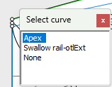
When several curves are edited, if you click between two control points a window will pop-up to let you choose the curve.
Here are all the design possibilities you have for the Top View and the Side View curves:
- In the Top View the most common design method is the work on the Apex curve (the curve corresponding to the control point defined as the Apex on the slices).
Then you can choose to also edit the Rail curve if you want more control on the Rail curve. You can also edit several of the bottom curves on the Top View to control the shape of the channels of a board for example:
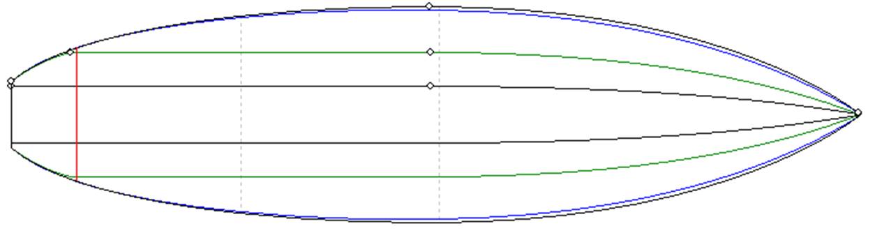
- If the slices don't have an Apex point defined, you can choose to work on the Outline curve. But then you won't be allowed to edit other curves like the Rail curve for example.
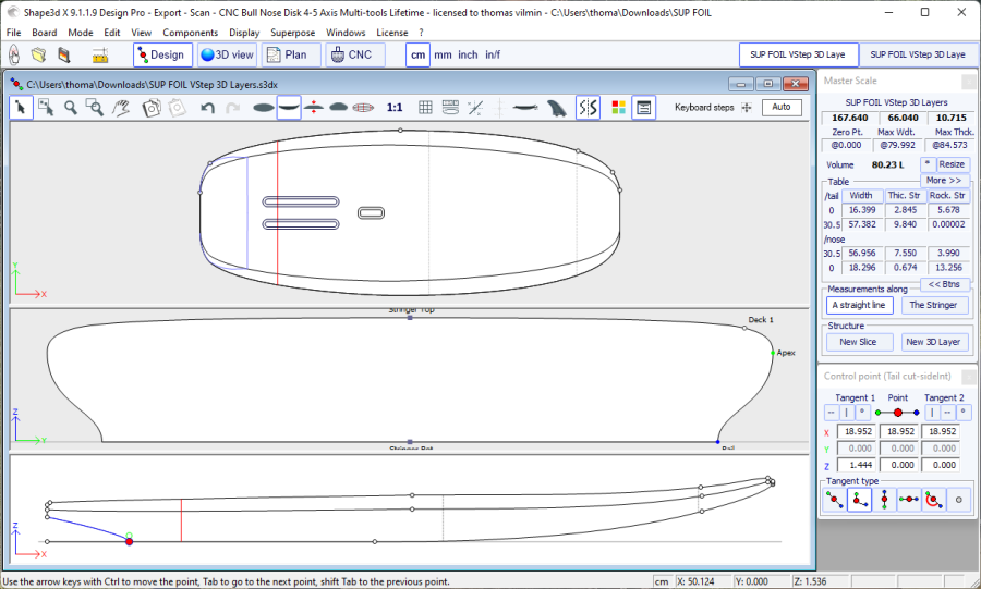
- In the Side View the most common design method is the work on the Bottom and Deck Stringer curves, which correspond to the first and last control points of the slices.
Then you can choose to also edit the Rail curve if you want more control on the Rail curve. You can also edit the Apex curve in the Side View, which can be very useful on some shapes like paddle boards:

- Another way of designing the side view is the work on the Bottom and Deck Profiles curves , which correspond to the shadow of the board. But then you won't be allowed to edit other curves like the Rail curve for example.
The Edited curves can be set Fixed to another edited curve ![]() . This means that the relative distance between the
two curves will stay constant when the second curve is modified. For
example one can set the Deck Stringer line Fixed to the Bottom
Stringer line, so that the stringer thickness doesn't change when
the Bottom Stringer line is modified. This thickness can be
displayed in the Thickness View.
. This means that the relative distance between the
two curves will stay constant when the second curve is modified. For
example one can set the Deck Stringer line Fixed to the Bottom
Stringer line, so that the stringer thickness doesn't change when
the Bottom Stringer line is modified. This thickness can be
displayed in the Thickness View.
If rail and stringer are both edited, you can choose to lock the rail line to the stringer line so that the depth of the concave or V doesn't change when you modify the stringer line. Then you can display the depth of the concave or V in the thickness panel and stretch it vertically to have a better view of the details...
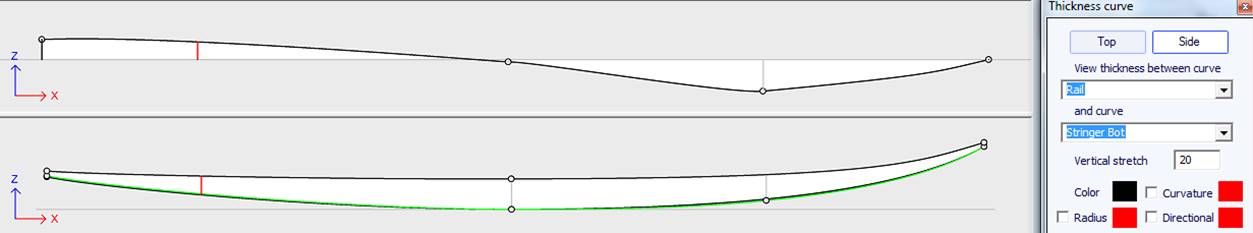
In the Thickness View, if the curve displayed corresponds to the thickness between a curve that is fixed to another one and this other curve, the control points appear and the curve can be modified. In this view the curvatures can be displayed, and the colors changed. Also the curve can be stretched vertically if it's too flat to be seen correctly.
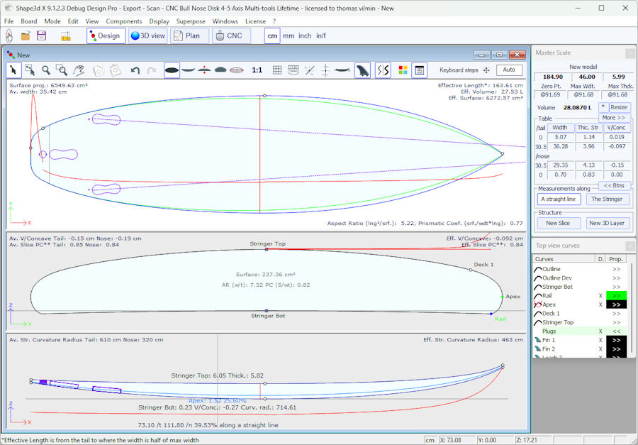
- With version 9.1.0.0 and higher, you can now edit the stringer curve in the top view:
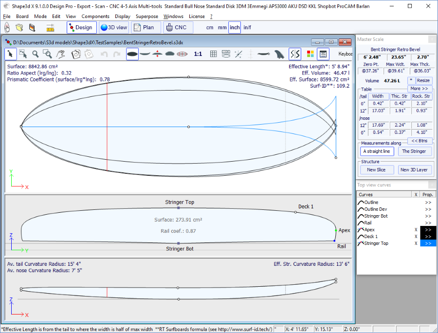
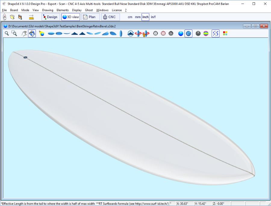
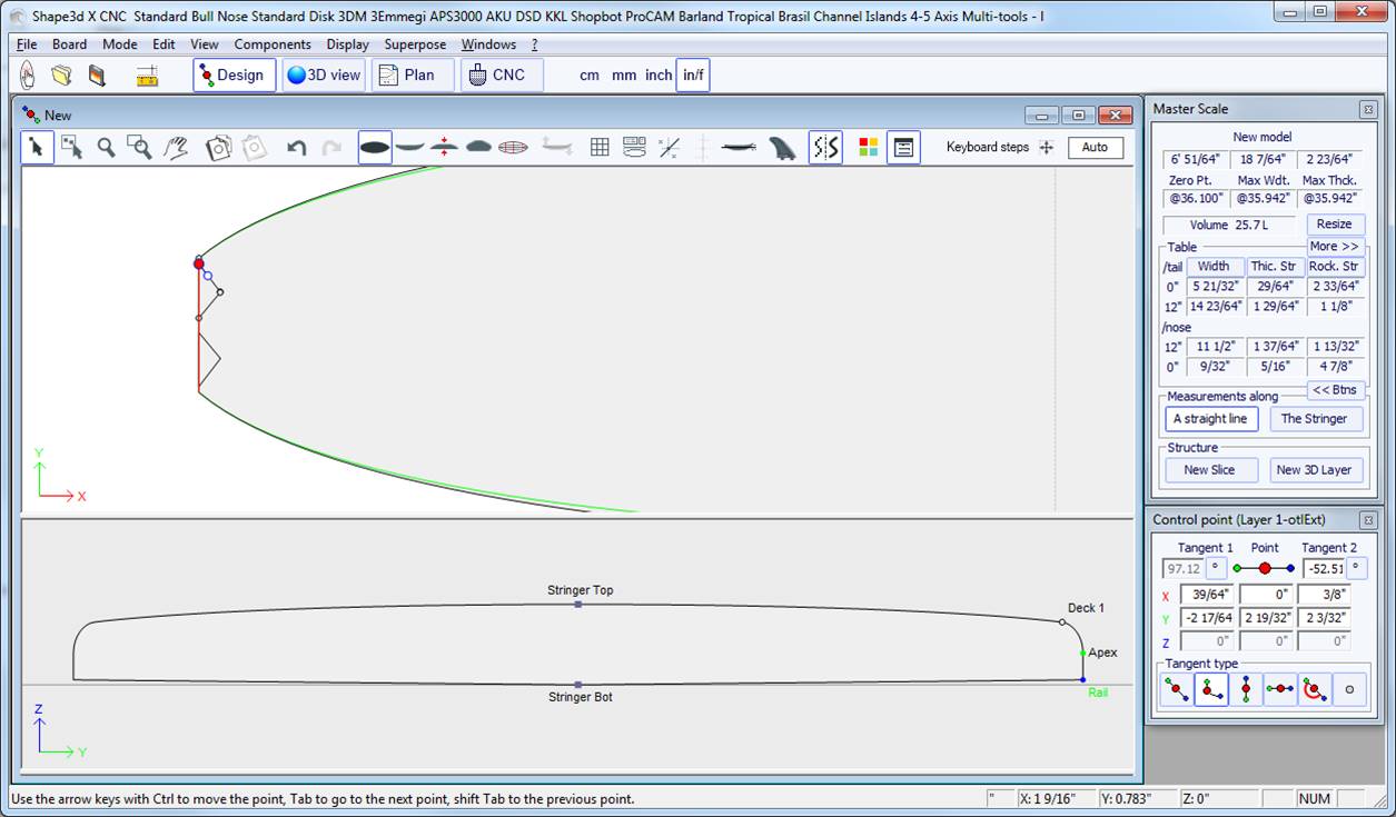
Bending the stringer curve (bottom or deck or both) in the Top view allows designing a Bevel nose,
because you can designe the slices past the center axis, and the final rendering will cut these slices along the center axis.
It also allows designing swallow tail:
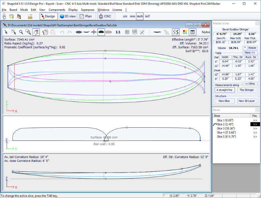
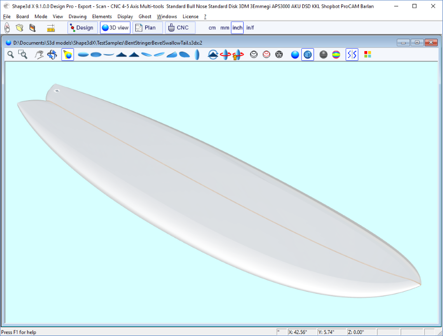
You can download these sample files in the Warehouse.
Note that the Multi-curves Edition needs the Pro option to be used.
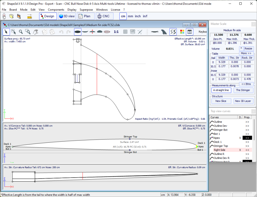
Version 9.1.0.0 and higher allows designing asymmetric boards. This also means you can design fins or foils! To release the symmetry constraint, just uncheck the "Symmetric right/left" option in the "Size and Parameters" window. The right hand side curves will then become editable in the Top and Side views, and also in the Slices view. The curves of both sides appear in the curves list window:
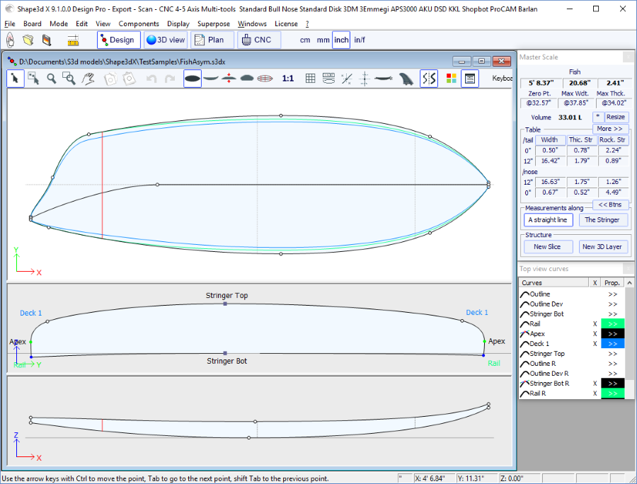
As the stringer curves of the Right hand side (bottom and/or deck) can be edited in the Top view, fins or foils can be easily designed:
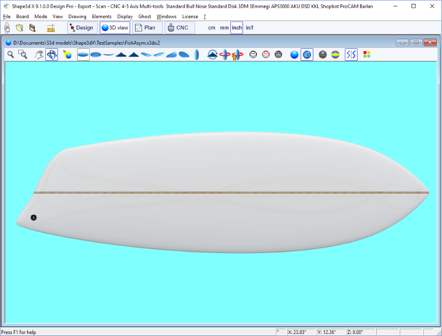
Note that editing the top view stringer curves on the Right hand side allows designing bent stringer on asymmetric boards, editing the top view stringer curves on the Left hand side allows designing bevel nose or swallow tails!
You can download these sample files in the Warehouse.
Note that Asymmetric models can only be designed using the Pro option.
The second most important new feature of Shape3d X is the possibility to add or subtract shapes to a board. These shapes are called 3D Layers. To add a 3D layer, simply click on the button New 3D Layer in the Master Scale window.
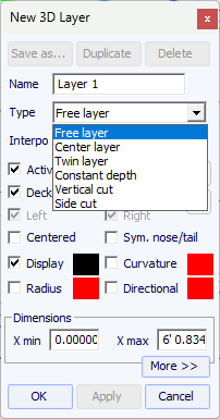
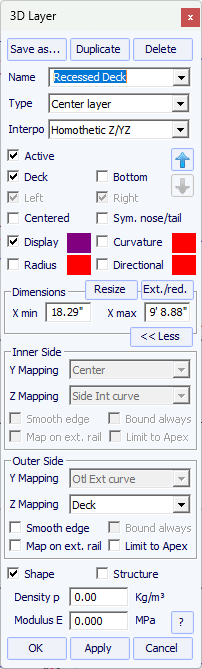
The 3D layers can be added to the deck or the bottom of the board. Its curves and curvatures can be displayed in any color. If the Active box is not checked, its shape won't be added in the 3D view or in the CNC mode. Once created, the 3D layer appears at the end of the curves list. The name can be changed.
On asymmetrical boards, the 3D layers can be positionned only on one side (left or right), or on both.
For nose/tail symmetrical boards, the 3D layers can be defined as "Centered X", which means that the center of the layer is at the center of the board. Or it can be set as "Symmetrical nose/tail", which means that it must be placed on the back half of the board, and will automatically be duplicated on the nose of the board symmetricaly.
There are 6 kinds of 3D layer:
- The Center layers ![]() are shapes which outline is designed in the Top View,
and the depth ( side curve) is defined in the side view.
are shapes which outline is designed in the Top View,
and the depth ( side curve) is defined in the side view.
It contains slices that are mapped on the board slices.
The width Y of the slices is set by the outline curve of the layer, and height Z of the center point is set by the side curve of the layer.
The last control point of the slices is stuck to the original board slice.
The number of slices is not limited.
In the resulting shape the volume between the original board slices and the 3D layer slices
is removed if the layer slices are inside the board slices, or added if they are outside.
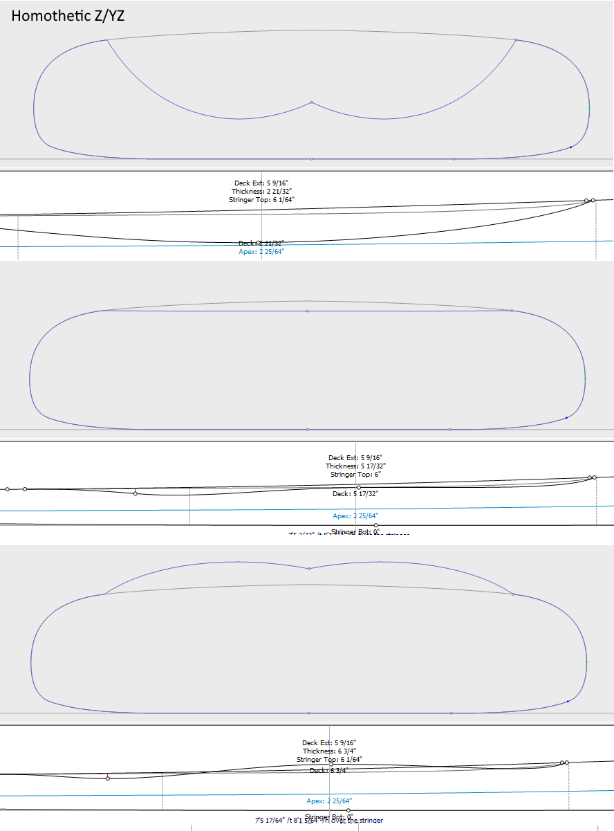
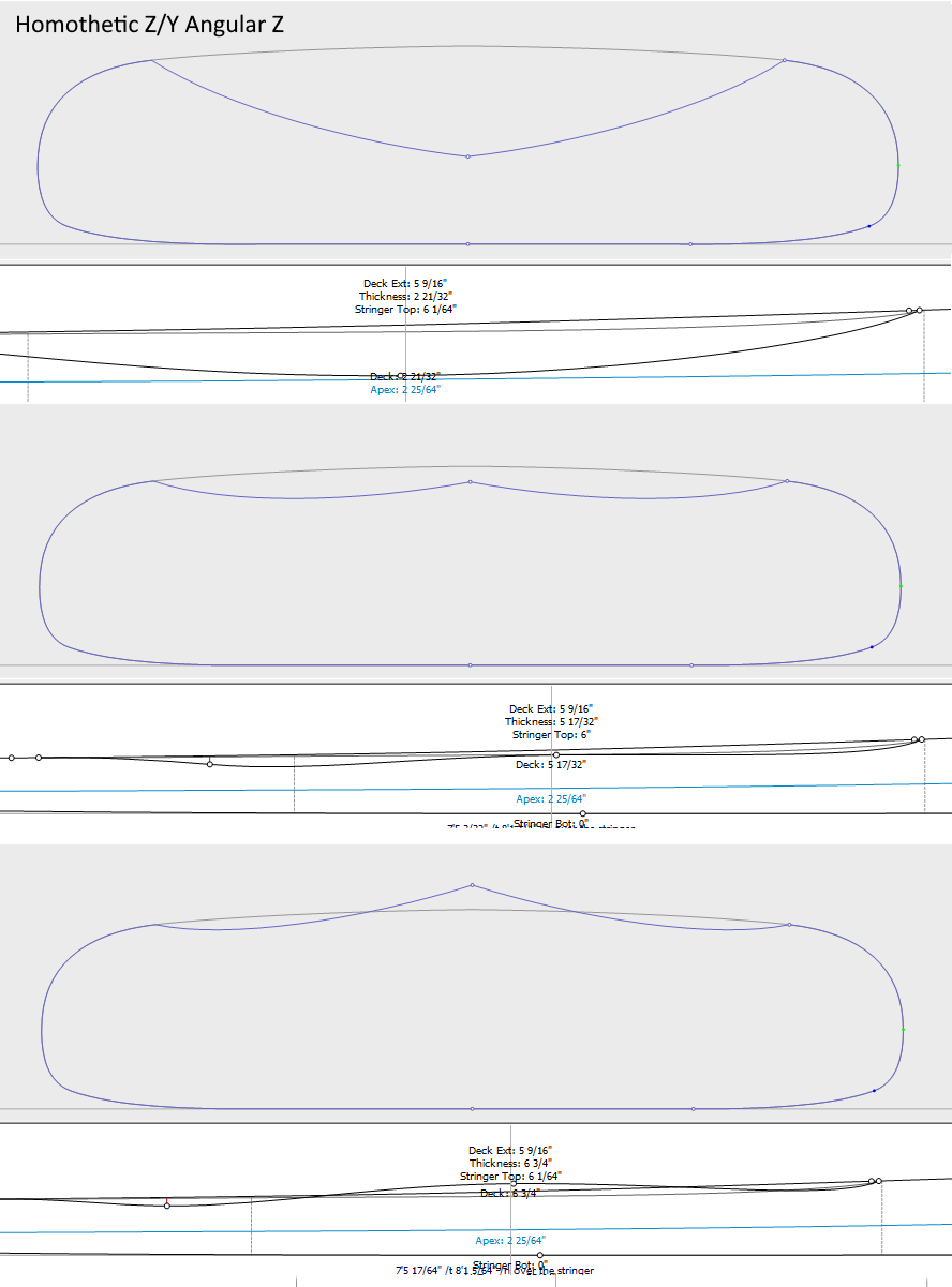
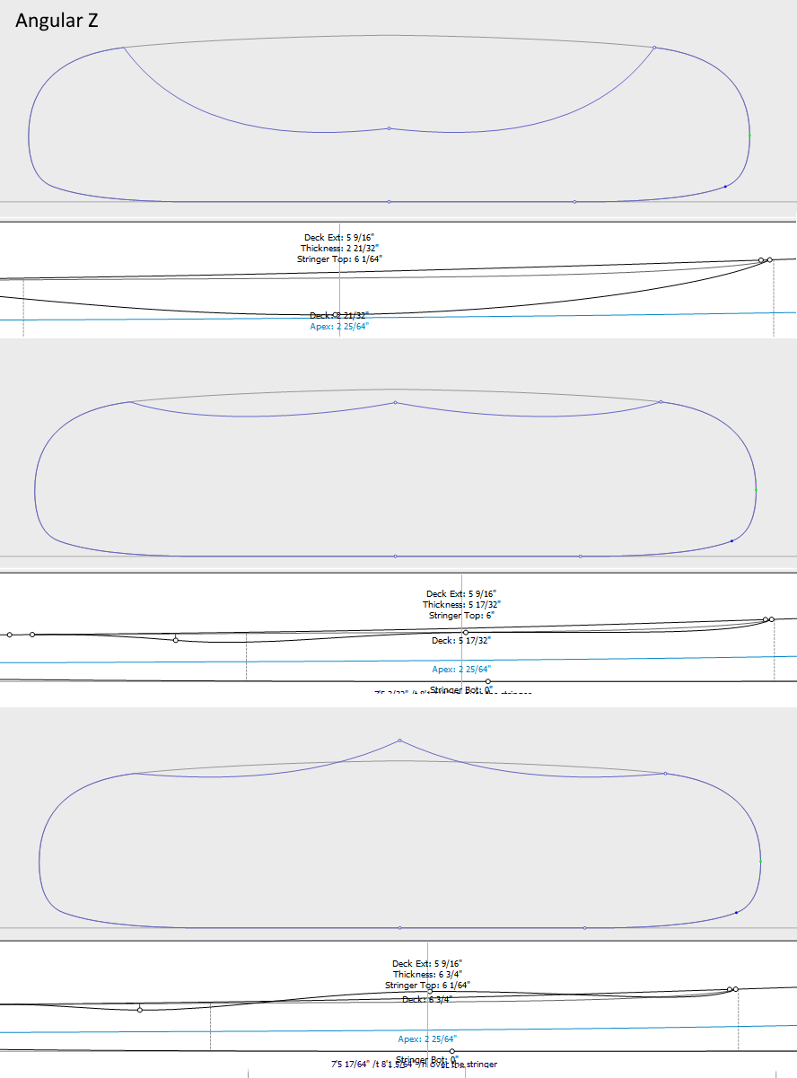
There are 3 interpolation modes: In the Homothetic Z/YZ mode, the height of the slices is rescaled homothetically with the width and with the ends Z variation. In the Angular Z mode the height of the slices doesn't depend on their width, it's adjusted with the angle of its ends. The Homothetic Z/Y Angular Z mode is a mix of the two other modes: the height of the slices is rescaled homothetically with the width, and then adjusted with the angle of its ends.

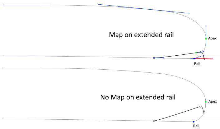
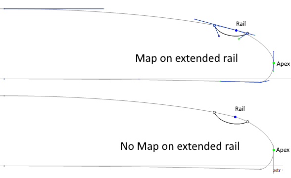
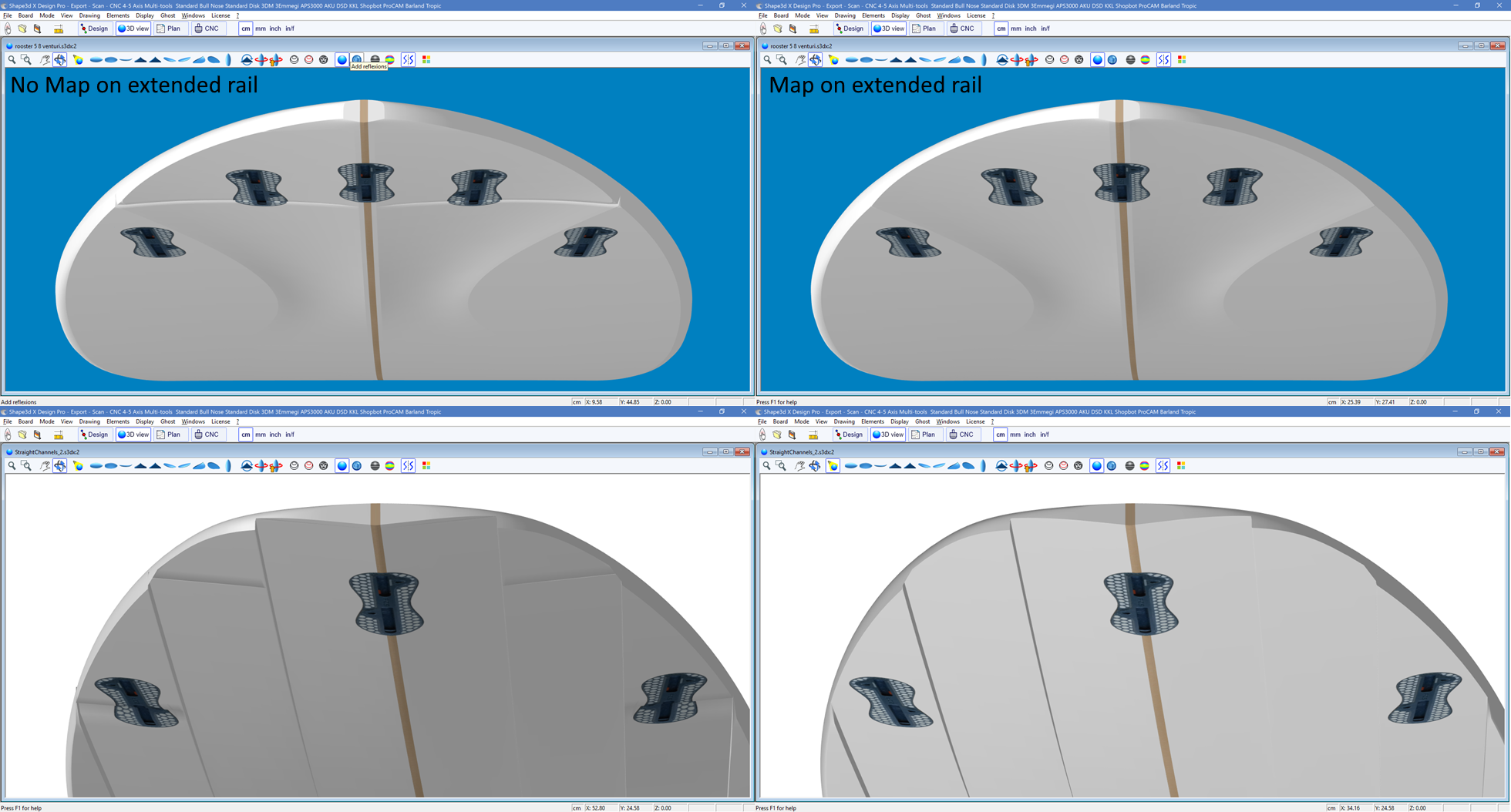
The option "Map on extended rail" allows mapping the layer's slices on a straight line extrapolated from the rail point. Note that since version 9.1.2.0 you can define a rail point on the bottom of the slices, but also on the deck.
The outer side of the layer can be mapped on the opposite side (i.e. Bottom for a Deck layer, or Deck for a Bottom 3D layer). For a deck 3D layer for example, the outer point of the layer's slices will be stuck on the bottom part of the board's original slices instead of the deck.
The option Smooth Edge on the inner or outer sides of the layer forces the first or last tangent of the slices to be parallel to the original slice, in order to get a smooth transition.
The option Smooth Trans. Xmin and Xmax inserts a slice at the beginning (Xmin) or end (Xmax) of the layer, and stick it to the original shape to ensure a smooth transition.
The addition of new slices is done through the menu Slices -> Add new slice on selected 3D layer.
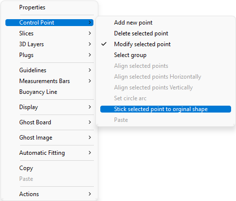
For smooth transition of the 3D layer's slice with the board's slice, the control point's tangents can be aligned with the board's slice curve with the menu Control Point -> Stick selected point to original shape.
The whole slice of the 3D layer can be stuck to the board's slice with the menu Slices -> Stick selected slice to original shape.
- The Twin layers ![]() is similar to a Center layer but it has an Outer outline curve Otl Ext
and an Inner outline curve Otl Int in the Top view.
is similar to a Center layer but it has an Outer outline curve Otl Ext
and an Inner outline curve Otl Int in the Top view.
There is no Side curve defining depth of the layer!
The depth is set by the slices that are mapped on the board slices.
The Y position of the first control point of the slices (the closest to the center) is set by the Otl Int curve,
and it is verticaly suck to the slice of the board.
The Y position of the last control point of the slices (the closest to the rail) is set by the Otl Ext curve,
and it is verticaly suck to the slice of the board.
The number of slices is not limited.
In the resulting shape the volume between the original board slices and the 3D layer slices
is removed if the layer slices are inside the board slices, or added if they are outside.
The options and the interpolation method, and the design of the slices, are the same as for Center layers.
Note that we more likely use the Angular Z interpolation mode for Twin layers
as the Homothetic Z/YZ mode gives bad results if the height difference between the inner and outer side changes sign.
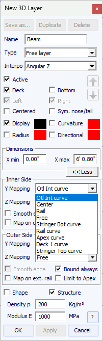
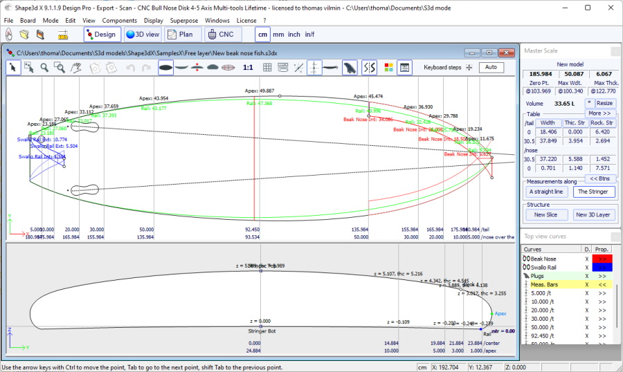
- Since version 9.1.2.0 a new 3D layers type has been added: the Free layers ![]() .
It is a combination of the Center layers and Twin layers with much more freedom and possibilities.
.
It is a combination of the Center layers and Twin layers with much more freedom and possibilities.
For the Inner and the Outer sides Top view definition (Y Mapping) you have the choice to use an Otl curve,
or any of the Definition curves of the original shape
(i.e. Apex curve, Rail curve...).
You can also set the Inner or the Outer sides to the Center,
or the Rail, or even let it Free.
For the Side view definition (Z Mapping) of the Inner and the Outer sides,
you also have the choice to use an Side curve,
or any of the Definition curves of the original shape.
And you can also choose to stick Inner or the Outer sides to the Bottom or Deck,
or the Original Bottom or Original Deck (i.e. the Bottom
or Deck before other 3D layers have been added).
You can also let it Free.
This allows you to have the maximum of control in the design of the 3D layer, and give new possibilities.
If you use an Otl curve for the Y Mapping, you can make the curve go past the center axis.
In this case the final shape will have the layer cut on the center axis.
This allows designing Swallow tail or Beak nose for example.
Here are some exemples of Inner side and Outer side mapping choices:

In this exemple above the Inner side Y is set to center, so the slices start on the center axis.
And the Z is set to Side Int curve, so the Side Int curve is displayed in the side view.
The first control point of the layer slices is fixed at Y = 0 and it's vertical position Z is set by the Side Int curve.
The Outer side Y is set to Otl Ext curve,
so the Y position of the last control point of the slices is set by the Otl Ext curve displayed in the top view.
The Z of the Outer side is set to Side Ext curve,
so the Side Ext curve is displayed in the side view,
and the Z position of the last control point of the slices is set by the Side Ext curve.
In the resulting shape the volume between the deck of the original board slices and the 3D layer slices
is removed here.
Note that if there's no intersection between the slices of the 3D layer and those of the board, the 3D layer has no influence on the final shape then.
This could happen here for exemple if you set the Side Int curve too high,
or the Side Ext curve too low.

In this exemple above the Inner side Y is set to Otl Int curve
displayed in the top view. And the Z is set to Bottom.
So the first control point of the layer slices (the closest to the center) has its Y position set by the Otl Int curve
and it's vertical position Z stuck the the bottom of the board slices.
The Outer side Y is set to Otl Ext curve,
so the Y position of the last control point of the slices is set by the Otl Ext curve displayed in the top view.
The Z of the Outer side is set to Deck,
so the Z of the last control point is stuck the the deck of the board slices.
Note that the Otl Int curve crosses the center axis to go to negative Y values, so the result is cut at Y = 0.
In the resulting shape the volume between the deck of the original board slices and the 3D layer slices
is removed here.

In this exemple above the Inner side Y is set to Otl Int curve
displayed in the top view. And the Z is set to Deck.
So the first control point of the layer slices (the closest to the center) has its Y position set by the Otl Int curve
and it's vertical position Z stuck the the deck of the board slices.
The Outer side Y and Z are set to Apex curve,
so the last control point of the slices is stuck to the Apex point of the original board slices.
Note that the Otl Int curve crosses the center axis to go to negative Y values, so the result is cut at Y = 0.
In the resulting shape the volume between the deck of the original board slices and the 3D layer slices
is removed here.

In this exemple above the Inner side Y and Z are set to Free,
so the first control point of the layer slices (the closest to the center) is not fixed horizontally nor vertically.
The Outer side Y is set to Rail (y max),
and the Z to Side Ext curve,
so the last control point of the slices is fixed vertically by the Side Ext curve curve,
and stuck horizontally to the board slices.
In the resulting shape the volume between the deck of the original board slices and the 3D layer slices
is removed here.
Note that if there's no intersection between the slices of the 3D layer and those of the board, the 3D layer has no influence on the final shape then.
This could happen here for exemple if first control point of the slices, which is free, is positionned too high here.
The option Bound always will connect the edge of the layer to the original shape vertically (or straight to the Apex if larger than the board). Note that when this option is not use and if the extremities of the layer slices are not stuck to the Bottom or Deck, then the final shape of the layer is the result of the intersection of its slices with the original shape slices. If no intersections the layer is not taken into account.
The other options and the interpolation method, and the design of the slices, are the same as for Center layers and Twin layers.
- The Constant Depth layers ![]() are shapes that are defined by
their depth and their outline designed in the outline view.
are shapes that are defined by
their depth and their outline designed in the outline view.
For the Inner and the Outer sides you have the choice to use an Otl curve, or set it to the Center or any of the Definition curves of the original shape (i.e. Apex curve, Rail curve...).
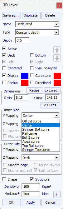
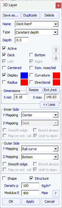
The outer side of the layer can also be mapped on the opposite side (i.e. Bottom for a Deck layer, or Deck for a Bottom 3D layer).

The option "Smooth edge" extends the layer to get a smooth transition at the edges instead of an angulous transition.
Note that you can apply a Constant Depth 3D layer on the whole board by setting xmin=0 and xmax=board length,
Inner mapping Y Center and Z Deck, Outer mapping Y Center and Z Bottom.
You can use such a layer evaluate the weight of the fiberglass stratification for exemple:
set the thickness (depth) about 1mm and the Density p.
For fiberglass lamination, a typical value is about 2000 Kg/m3.
You can also let the thickness (depth) to 0, and then the density p will be the surface density.
For a 1mm thick fiberglass lamination, a typical value is about about 2 Kg/m2.
Then you'll get the weight in the Plan mode / Volume and Surface distribution.
- The Side Cut layers ![]() are shapes that are defined by a curve Side in the Side view that cuts the board horizontaly.
are shapes that are defined by a curve Side in the Side view that cuts the board horizontaly.
- The Vertical Cut layers ![]() cut the board vertically.
They can be defined by their outline curves Otl Int and Otl Ext
designed in the top view, that cut verticaly and removes the volume between them.
cut the board vertically.
They can be defined by their outline curves Otl Int and Otl Ext
designed in the top view, that cut verticaly and removes the volume between them.
The Inner side Y mapping can also be set to Center instead of Otl Int
when a single shape is cut at the center of the board (for a swallow tail for exemple).
The Outer side Y mapping can also be set to Rail (ymax) instead of Otl Ext
when the whole rail is cut (for wings for exemple).
Note that the Vertical Cut layers are cut from the deck by default. But since version 9.1.2.8 they can be set on the Bottom.
This allows to cut it in the CNC mode at the end of the bottom cut instead of the deck.
The 3D layers can be saved in a separated file, and then loaded in another board file using the menu "3D Layers" -> "Load 3D layer". They can also be deleted from the board design.
Several 3D layers can be added one on the other.
There are several Resizing options that let you choose whether the 3D layer should be resized proportionally in length or width when the board is resized.
The 3D layer can be part of a "Group" and "Locked" so that the layer and the group can only be moved as a block.
The 3D layers can be define as a "Shape" or as a "Structure"
(i.e. a reinforcement patch for exemple).
In the second case you can define the density so that it is used in the final weight computation, and the elastic modulus for the stifness computation.
If the 3D layer is defined as a "Structure" and not "Shape" ,
then it is not taken into account in the auto-positioning of the plugs.
You can download some sample files in the Warehouse.
Note that the 3D Layers need the Pro option to be used.

![]() Editing
mode
Editing
mode
![]() Group
selection
Group
selection
This feature allows selecting a group of control points or a group of guidelines if the guidelines are shown on screen.
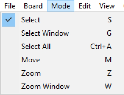
![]() Zoom
Zoom
![]() Zoom
Window
Zoom
Window
In this mode, if you draw a rectangle with the mouse, the view is enlarged and the contents of the rectangle are fitted to the pane view. Right click to zoom back.
![]() Move
Move
Move the drawing with the mouse.
These functions are also present in the menu "Mode".
![]()
![]() Copy and paste
Copy and paste
You can copy the active curve (outline, rocker, thickness)
by clicking on the ![]() button
and paste it with
button
and paste it with ![]() on another curve
of the same board or of another board.
on another curve
of the same board or of another board.
You can also copy a slice and paste it on another one. If you paste it on the slice of another board they need to have the same number of control points per slice.
For exemple, to get smooth lines at the nose when it's veru thin, it's recommended to copy the slice next to the nose slice and paste it on the nose slice.
It's easier than to edit the nose slice which can be very small.
Note that if you select one control point of the copied curve, and then one point of the other curve, it will copy-paste the whole curve.
But you can also copy-paste just a section of curve by selecting the control points you want (press the Shift or Control keys while selecting the points).
It's also possible to copy and paste just one control point, but in this case you need to use the function "Paste on selected point"
in the Control points menu.
Copy and paste can also be done pressing the keys Ctrl+C and Ctrl+V (see The Shortcuts).
These functions are also present in the menu "Edit".
![]()
![]() Undo
and Redo
Undo
and Redo
Undo the last actions (add, move or delete point or guidelines...). Now with Shape3d X you can also Redo the last action you Undo.
![]()
![]()
![]()
![]() Change
view
Change
view
You can change the order of the views: put slices on top instead of outline for example. You can also change the size of each pane by moving the bar between the panes.
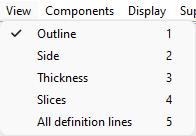
![]() Top view
Top view
The Top view allows seeing all the definition curves from the top.
![]() Side view
Side view
The Side view allows seeing all the definition curves from the side.
![]() Thickness view
Thickness view
The Thickness view allows displaying the distance between two curves; like the thickness between the bottom and the deck stringer curve for example.
![]() Slices
Slices
![]() Wire view
Wire view
This view is very useful to check the smoothness of the lines and enable you to move the control points of the slices directly on the 3D view of the board. Click on a point to show its tangents and to move it. Be careful, it's not as easy as in the 2D view!
To rotate the board, move your cursor in a free area and you will
see the symbol of the cursor will change too ![]() .
.
By moving the board with the mouse, you can check the smoothness of the curves, as it gives you a "compressed view" of the curvature.
 Rotate View
Rotate the selected view to display the design vertically.
![]() Full Scale mode (1:1)
Full Scale mode (1:1)
Shows the curves in the selected panel in real size. Some screens need a correction coefficient that you can define in the Preferences window (menu File)
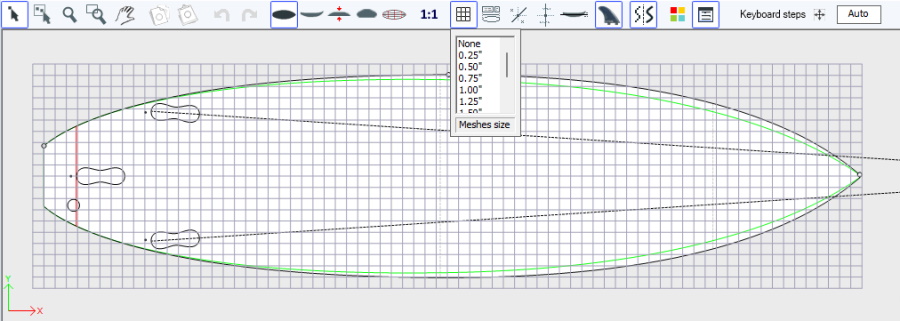
![]() Grid
Grid
Click on this button; choose the step of the grid and display a grid on the active pane.
![]() Rail Master
Rail Master
The Rail master will display the measurements in the selected panel, as well as the percentage of change since last time you saved the file.
![]() Guidelines
Guidelines
This button displays the guidelines associated to each edited curve. We'll see in the Menu chapter how to add, delete or move a guideline, and also how to automatically fit a curve to its guidelines.
Note that the Guidelines need the Design option to be used.
![]() Measurement bars
Measurement bars
This button allows displaying the measurement bars that gives the measurements of all the displayed curves of a panel at a defined distance from tail or nose.
You can add labels to the measurement bars and the expected precision.
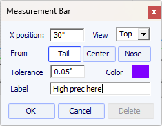
Note that the Measurement bars need the Design option to be used.
![]() Buoyancy line
Buoyancy line
This button displays the Buoyancy line in the Side view panel. The Buoyancy line gives the volume below and above a chosen height.
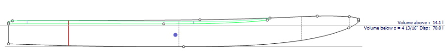
Note that the Buoyancy line need the Pro option to be used.
![]() Fin boxes
Fin boxes
This button displays the boxes, if you have defined fin boxes, or
foot straps or mast foot for your board. You can move them with the mouse or the keyboard arrows.
See menu Components/Plugs for more details.
![]() Logos
Logos
This button displays the logos that will be mapped in the 3D view. You can move them with the mouse or the keyboard arrows.
See menu Components/Logos for more details.
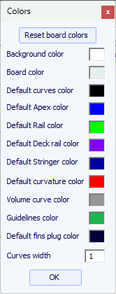
![]() Colors box
Colors box
Press this button to change the color of the background, the board, or default color of the curves. The default curves color apply if the curves are black. The default curvature color apply if the curvature of a curve is red. You can also change the curves line width.
Master Scale
Press this button to have the Master Scale, the Curves List, the Guidelines List and the Point Properties boxes shown on screen, or disappear.
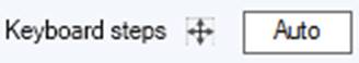
You can define the steps of the keyboard displacements. If you let it blank, it will go back to Auto. With Auto, the more you zoom in the smaller the steps. If you press the Shift key the steps will be 2 times smaller. With Ctrl it will be 4 times smaller. And Shift+Ctrl makes them 10 times smaller.
Smart Functions
Press this button open or hide the Smart Functions window.

Most of the options presented in the Menu are also accessible in the toolbar. However, some of them are not:
Note that all menus and submenus are accessible from the "Search..." field of the main toolbar.
"Save" will save your file with the .s3dx extension, which is the Shape3d X format.
The .s3dx files cannot be opened by Shape3d V8 or older! This is because the VX files can contains objects like the 3D layers or edited curves that are not handled by Shape3d V8 and older.
But you can save your files with the .s3d extension in the V8 format using "Save as..."
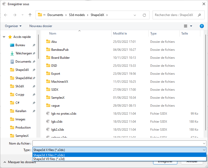
In this case, if your board has 3D layers, or multi-edited curves, they will be removed from the .s3d V8 file.
The menu item "Preferences..." opens the preferences dialog box.
The "Print" item allows printing the current view.
The option "Viewer" opens the viewer that allows visualizing data files in 3 dimensions.
The option "Scan import..." opens the Scan dialog box.
The "Shape3d Warehouse" allows downloading sample boards and sharing your boards on the ../Warehouse web site.
The menu "Board" allows displaying the Properties window of the board (see Size and Parameters).
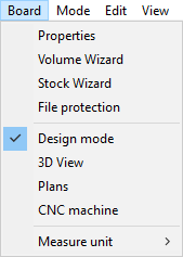
- It also allows opening the Volume Wizard (see Master Scale window).
Note that the Volume Wizard needs the Design option to be used.
- And the Stock Wizard that allows generating a list of dimensions with volumes for a range of length and width/thickness variations. It can save all the stock files in a target folder:
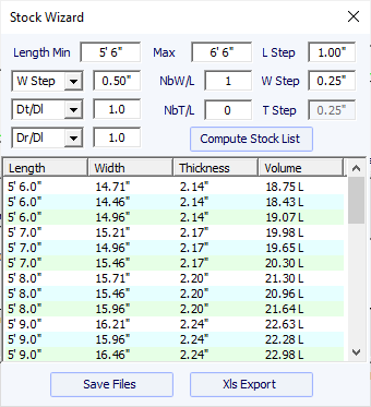
While the length is resized, you can either set a fixed width variation W Step, or set the width variation over length variation ration Dw/Dl. By default Dw/Dl for constant proportions resizing.
You can set the thickness and rocker variations the same way.
Then, for each stock length, you can create several stock widths setting the NbW/L field larger then 0. If NbW/L is set to 1, at each length you'll get a stock board with the width lowered by W Step
and one with the width encreased by W Step. You can do the same with the thickness.
The Stock Wizard window also allows loading stock dimensions from a txt or CSV file. You can then create a s3dx file for each stock dimension in a click.
Note that the Stock Wizard needs the Pro option to be used.
- You can access the File protection tab of the Size and Parameters window directly from this menu.
- This menu also allows changing the general mode and the measurements unit.
The menu "Mode" allows changing the selection mode in the design panels.
The menu "Edit" ) contains the Copy-Paste functions, and Undo-Redo.

The menu "View" allows changing the view of the active panel (see toolbar). It also includes the option to display the board vertically.
The menu "Components" allows modifying the design components of the boards.
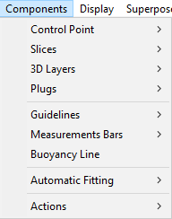
"Control points" allows adding a new control point, deleting the selected point, modifying the selected point, or activating the Group selection function.
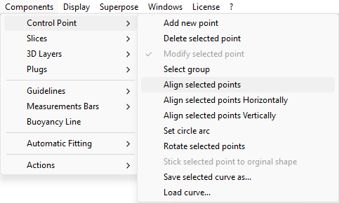
If several control points are selected, "Align selected points" allows aligning several points and tangents of a curve. The points can also be aligned horizontally or vertically.
"Set circle arc" modify the selected curve sections (2 or more control points) to approximate a circle arc (i.e. constant curvature).
"Shift selected points" will shift the selected curve sections perpenducularly to the curve by a distance you choose.
"Rotate selected points" allows rotating the section of a curve, or the whole curve in its plan. It can be used to tilt the cross section of an hydrofoil for exemple.
"Stick selected point to original shape" allows positioning the control point of a 3D layer's slice right on the original slices.
"Stick selected point to Ghost" allows positioning the control point on the closest point of the loaded Ghost.
"Paste on selected point" is active when one control point has been copied, and only one other control point is selected. It allows for copy-pasting only one point instead of the whole curve.
The selected curve can be saved in a separate file using "Save selected curve as...". It can also be loaded from a curve file or a board file using "Load curve...".
"Clear all fixed points" removes all the constraints that fix a control point to another one.
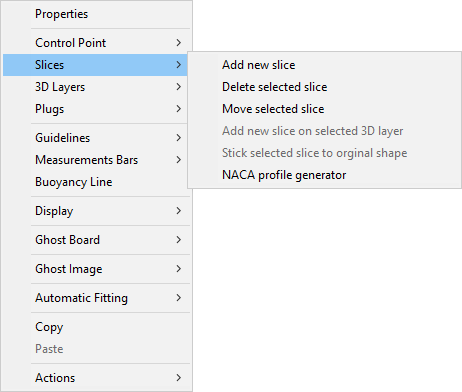
"Slices" allows adding a new slice, deleting or moving the selected slice.
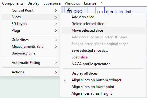
The selected slice can be saved in a separate file. It can also be loaded from a slice file or a board file.
This menu also allows you to modify the slice display options:
All Slices shows all the slices at once in the Slice panel.
There are 3 choices for the vertical alignment of the slices when several of them are displayed, or when a ghost board is displayed:
Align slices on bottom stringer, Align slices on lower point, and Align slices at real height.
This option will also change the Z value of the slice control points displayed in the control points properties window.
- With Align slices on bottom stringer the center point of the bottom of each slice will be set at Z=0.
- With Align slices on lower point the lowest control point of each slice will be set at Z=0.
- With Align slices at real height the slices will be placed at their real height as shown in the side view.
Note that you need to select the option Aligned on real height to be able to move the slices of a ghost up of down.
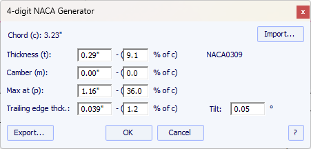
Note that the NACA window needs the Pro option to be used.
"3D Layers" allows adding a new 3D layer, deleting or moving the selected 3D layer, or saving the selected 3D layer in a file and loading a 3D layer from a 3D layer file or another board file.
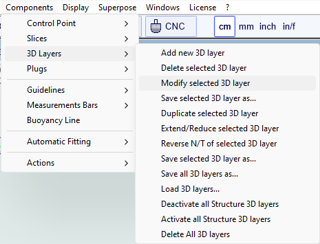
The selected 3D layer can be duplicated, extended/reduced or reversed.
You can also save all the 3D layers in a new file, and then load them in
another board file.
Note that the 3D layers need the Pro option to be used.
The plugs are elements that can be added on your design in Shape3d to render for the surfboard fin plugs, or leash plugs,
or windsurf mast track or footstrap inserts, or any other rectangular or circular shape
that should be added inside your design. The most common surfboard fin and leash plug brands are available in Shape3d (FCS, Futures Fin, Chinook...). You can also define your
own custom plugs setting the dimensions and corner radius.
The "Plugs" menu allows adding a new plug, or modifying the selected plug. It also allows saving plugs
in a separated file, or load plugs from a plug file or another board file.
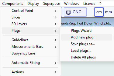
The "Plugs Wizard" allows adding several fin plugs or foot straps plugs at the same time.
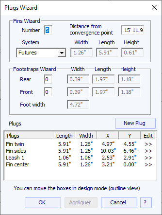
You can find a good guide for fin placement on McKee Surf website: http://www.mckeesurf.com/?page_id=267.
For a surfboard with thrusters, the convergence point can be positioned along the stringer.

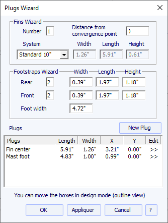
For a sail board, only one fin box can be defined. On the other hand, the number of foot straps is not constrained.
Additional plugs can be added with the button New Plug. The new plugs can be boxes, leash plugs, or fins plugs of any type.
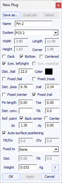
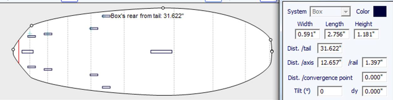
The System of the new plug can be of any standard system, or a simple box or cylinder.
For boxes and cylinders the dimensions can be changed. For boxes with rounded corners you can define a corner radius.
For cylinder plugs, the length can be different from the width to give oval shape.
The plug can be a single plug, "Centered Y" or not,
or twin boxes "Sym. right/left" (one on each side of the board).
The option "Sym. nose/tail" also allows duplicating the plug, placed on the tail, to the nose.
The X position is defined from the tail of the board, and the Y position can be defined from the center axis or from the rail (Apex curve).
In case of resizing of the board, the X position of the plug can be set "Fixed to tail" or "Fixed to nose".
If none of these boxes are checked, the X poition of the plug will change proportionaly to the length of the board.
In the same way, the Y position of the plug can be set "Fixed to center" or "Fixed to rail", or none.
If "Fixed to rail" the plug will be moved when you modify the Apex curve in the top view.
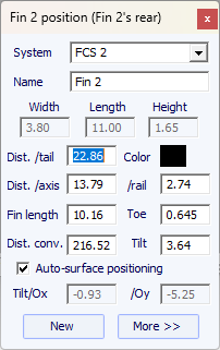
The "Reference point" can either be the center of the back of the plug, with dx and dy shift, or the center of the plug.
For standard fin systems like FCS or Futures, the reference point is set by default and corresponds to the rear of the fin.
The tilt angle can also be modified in 3 different ways:
- Change the Toe, or the Fin length (Toe/Fin length = tan(Tilt))
- Change the Distance to convergence point (Dist. axis/Dist. conv = tan(Tilt))
- Or change the Tilt angle in degrees.
The "Auto-surface positioning" option place the plug right at the surface of the board.
Note that the 3D layers defined as "Structure" are not taken into account in the auto-positioning of the plugs.
If this option in unchecked, you can set the tilt angles, relatively to the Ox axis and to the Oy axis.
The plug can be "Fixed to" another plug. The distance and angle can be set manually.
The "Constr. depth Z margin" and "Constr. width Y margin"
are the margins added in the CNC mode or in the 3D exports.
You can define the weight so that it is added to the total weight of the board.
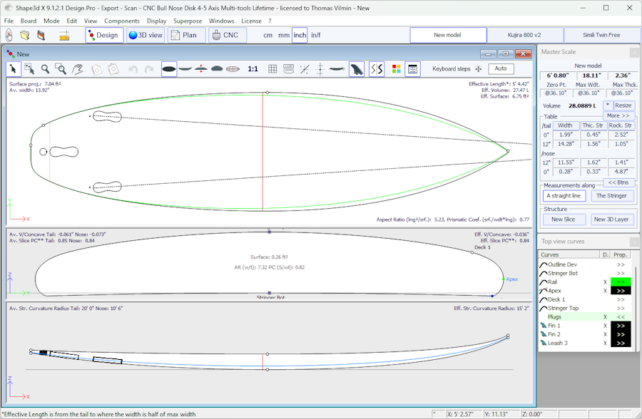
The plugs are displayed in the Top view, in the Side view, and in the slices view.
The list of plugs is also added to the list of curves. The X in the list allows you to display or hide each plug.
When you click on a plug in the Top view panel, the label of the plug is displayed, and the properties window appear on the side.
The label can be selected and moved with the mouse or keyboard. The position of the label will be the same in the print sheet of the Plan mode.
Since version 9.1.3.0 the function "Convert plugs to 3D layers" allows converting all the plugs into 3D layers that have the same shape and that you can modify afterward.
Note that the Plugs need the Design option to be used.
Since version 9.1.3.0 the logo images mapped on the 3D view can be added and modified in the Design mode!

The logos can be moved, rotated and resized directly in the top view of the Design mode, with the mouse or the arrows of the keyboard. In addition, thanks to the Design+3D mode, you can watch the logos mapped on your board in real time during your modifications.

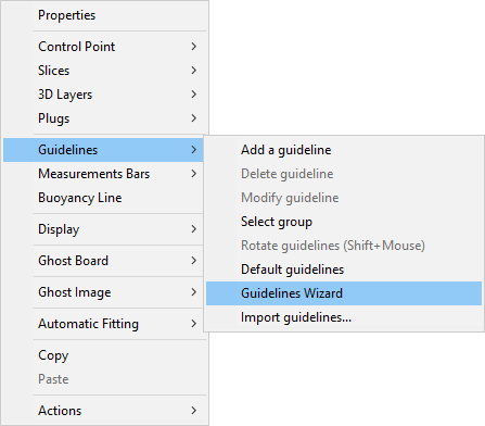
"Guidelines" allows adding a new guideline, deleting or moving the selected guideline, or activating the Group selection function. "Default guidelines will create" guidelines at fixed distance from tail and nose that correspond to the selected curve. "Guideline wizard" open the Measurement Wizard window (see New board from measurements). "Import guidelines" allows importing guidelines from a file (.dxf, .txt, .asc, .csv, .pim).
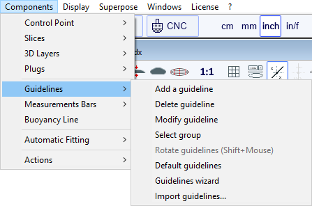
Note that the Guidelines need the Design option to be used.
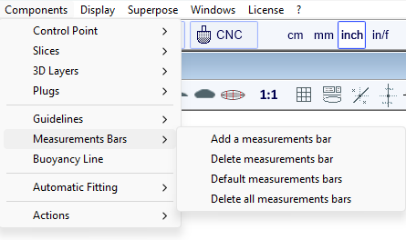
"Measurement Bars" allows adding or deleting a measurement bar. A measurement bar guives the measurements of all the displayed curves at a gives x position from the nose or the tail. "Default measurement bars" will create measurement bars at fixed distance from tail and nose. "Delete all the measurement bars" will delete all the measurement bars in the active view.
Note that the Measurement Bars need the Design option to be used.
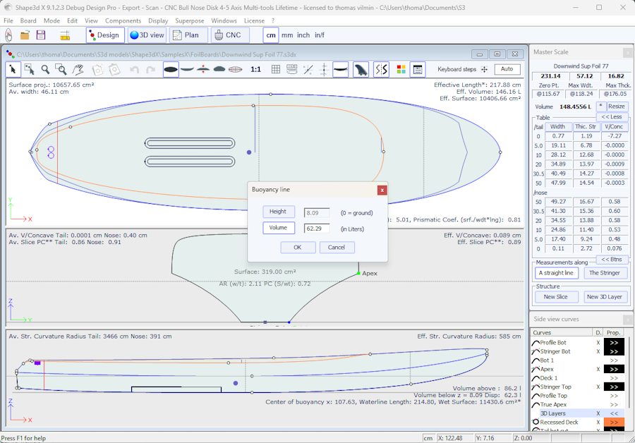
"Buoyancy Line" allows defining the displacement volume, or the height of the buoyancy line.
Once the buoyancy line is defined it will display the volume below and above, as well as the waterline length and the wet surface in the side view.
You'll also see the waterline and the center of buoyancy in the top view.
Note that in order to float, the volume of the board in Liters must be larger than the total of the weight of the rider plus the weight of the board in Kg.
To evaluate the buoyancy line, the buoyancy volume must be set equal to the total of the weight of the rider plus the weight of the board in Kg.
Shape3d also gives the "Metacenter height", which is an indication on the lateral stability of the shape
(see Hydrostatic Stability curves in the Plan mode).
Note that the Buoyancy Line need the Pro option to be used.
"Automatic Fitting" allows fitting an arc (the section of curve between two control points) or a whole curve to the guidelines or to the curve of an STL ghost board.
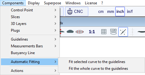
If you click on a curve section between two control points and choose "Fit selected curve to the guidelines", it will show the Guidelines fitting window.
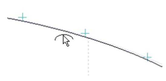
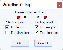
Then you have to choose if you want to adjust the length or the direction of each tangent, or both. And press OK.
You can also choose to adjust the whole curve, clicking on "Fit the whole curve to the guidelines".
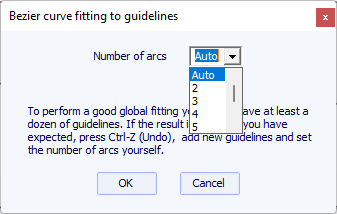
In this case you can choose the number of arcs (i.e. number of control points minus one) that will compose the whole curve. "Auto" will set it automatically, depending on the shape of the curve.
Note that the Automatic Fitting needs the Pro option to be used.
The "Actions" menu contains several items:
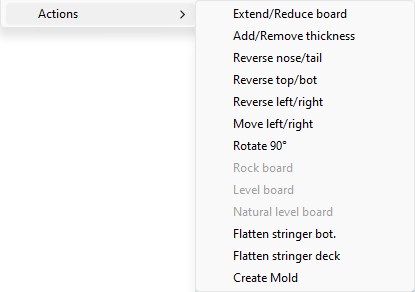
- "Extend/Reduce board" allows increasing or reducing the
length of the board without changing the rest of the board shape (Design option needed).
You can either extend/reduce the "Tips":

- Or a "Section" of the board defined x range:

- "Add/Remove thickness" allows adding or removing some thickness all over the board (Pro option needed). Note that this function will give distortions if the shape is too complex.
- "Reverse nose/tail" changes the board direction (Design option needed).
- "Reverse top/bot" flips the board upside down (Design option needed).
- "Reverse left/right" gives a mirrored board for asymmetric boards (Pro option needed).
- "Rotate 90 Deg" switch the Top and Side views. If the board is not yet asymmetrical, it becomes so (Pro option needed).
- "Rock board" allows tilting the stringer or the board (Design option needed).
- "Level board" rocks the profile view so that the tail and nose rocker are identical (Design option needed).
- "Natural level board" rocks the board so that the rocker is the one the board would have while lying on the ground (Design option needed).
- "Flatten stringer bot." sets the tail and nose rocker to zero, keeping the thickness unchanged. This function sets the bottom stringer straight (Design option needed).
- "Flatten stringer deck" flattens the deck of the board, keeping the thickness unchanged. This function sets the deck stringer straight (Design option needed).
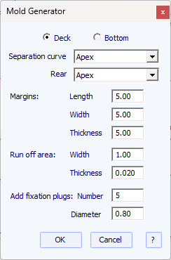
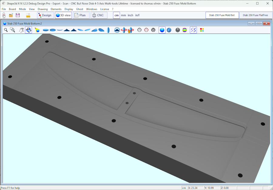
- "Create Mold" opens the Mold Generator window, that allows creating a mold of the deck or bottom of your design (Pro option needed). You can select the separation curves, and add margins and a run off area:
All these function can be accessed through the contextual menu (Right-click).
The menu "Display" allows displaying or hiding curvatures, guidelines, measurements bars, waterline, fins plugs, and grid in each design panel.
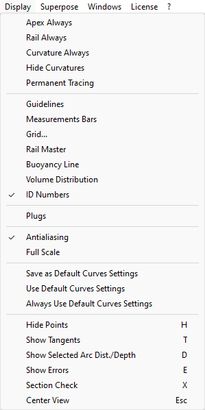
Apex Always shows a red mark at the widest point of the slices.
Rail Always shows the rail curves on all boards, even if not set as displayed.
Curvature Always shows the curvature of the selected curve.
Hide Curvatures hides the curvates of all curves and slices.
Permanent Tracing shows the measurements of the displayed curves at the position of the mouse even if the left button is not pressed.
Saved Curve shows the original curve when you are moving a control point or a tangent.
Plugs shows the plugs in the selected panel.
Logos shows the logos in the top view panel.
Guidelines shows or hides the guidelines.
Measurements Bars shows or hides the measurements bars.
Grid... shows a grid behing the board curves.
Rail Master shows the main measurements in the selected panel.
Buoyancy Line shows or hides the buoyancy line.
Volume Distribution shows the volume distribution curve in the Side view.
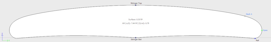
ID Numbers shows main geometric numbers that characterize a board:
- Surface: projected surface of the outline
- Ratio Aspect (lng²/srf.): squared length over projected surface ratio
- Prismatic Coefficient (surface/wdt*lng): outline surface over rectangle wdt*lng surface ratio
- Av. tail Curvature Radius: average curvature of the bottom stringer curve between the tail and the middle of the board
- Av. nose Curvature Radius: average curvature of the bottom stringer curve between the nose and the middle of the board
- The Slice PC (called Rail Coefficient in previous versions) is the prismatic coefficient of the slices: ratio of the slice surface over the surface of a squared slice
- Effective Length: distance between the tail and the point where the width is half of maximum width
The Effective Length stays the same whether you set a rounder or thinner nose tip.
- Eff. Volume: volume of the board between the tail and the effective length
- Eff. Str. Curvature Radius: average curvature of the bottom stringer curve between the tail and the effective length
- If the Buoyancy line is displayed, the "Maximum section area", the "Waterplan coefficient" and the "Block coefficient" are also given.
- It also add the % of total width or thickness to the tracing measurements:
for exemple in the side view if the stringer curves and the apex curve are displayed,
the measures shown when you move the mose will show the height of the Apex in % so you can see if the rail is a 50% (50/50) rail,
or 40% (60/40) or else.
Full Scale (1:1) shows the curves in the selected panel in real size. Some screens need a correction coefficient that you can define in the Preferences window (menu File).
Save as Default Curves Settings saves the display options
Use as Default Curves Settings loads the saved display options
Always Use Default Curves Settings loads the saved display options each time you open a new file
Hide Points hides the control points to have a clearer view of the curves. You can also press the H key to activate this function.
Show Tangents displays the tangents of all the control points to check the whole curve at once. You can also press the T key to activate this function.
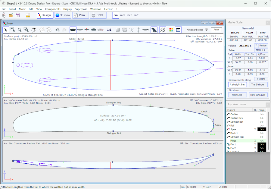
Show Selected Arc Depth displays the maximum depth of the selected curve arc. The curve arc developped length and tilt angles are also displayed in the bottom bar. This function is usefull to measure double concave depth for example. You can also press the D key to activate this function.
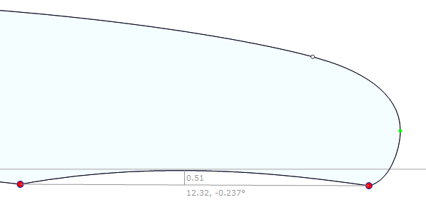
Show Errors releales design mistakes, like superposed slices or superposed control points (big green spot), loops or crossing tangents (big red spot). You can also press the E key to activate this function.
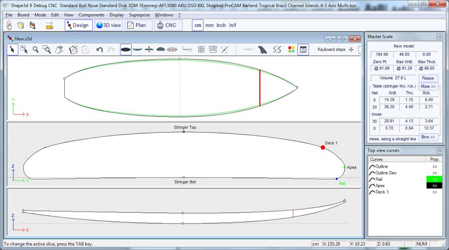
Section Check displays in the Slice panel the cross section of the board at the position of the mouse
in the Top or Side view panels. You can also press the X key to activate this function.
Note that Section Check doesn't change anything if the Permanent Tracing option is on.
Center View places the board at the center of the panel. You can also press the Escape key to
activate this function.
All these function can be accessed through the contextual menu (Right-click).
The menu "Superpose" allows displaying another board or a picture behind the curves.
You can choose another board and load it as a ghost board. The ghost board appears in each view in the color you choose.
It can be moved with the mouse. Press Shift to rotate the ghost in the Side view.
Note that you need to select the option Aligned on real height in the menu Components / Slices
to be able to move the slices of a ghost up of down.
You can also compare the slices flow of the two boards.
Up to 10 ghosts can be loaded at the same time, and you can select the curves you want to display for each ghost in the curves list window.
Note that you can use the ghost in the 3D view and also in the Plan mode.
Press the space bar to hide the ghost.
Note that you can load an STL or IGES file as a ghost.
The Ghost Properties window allows movig and rotating the ghost.
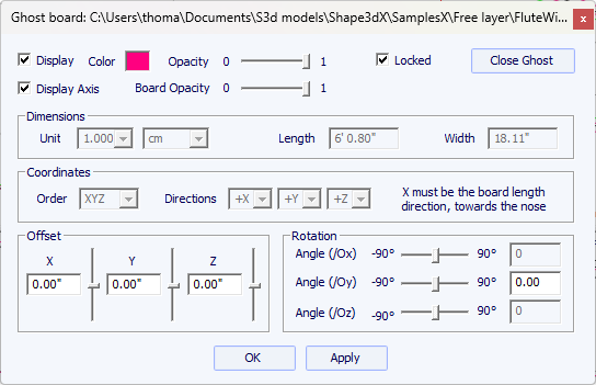
Note that you need the Design option to load a Shape3d file as a ghost, and the Pro option to load an STL file as a ghost.
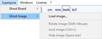
You can load an image in the background to copy an outline or a profile.
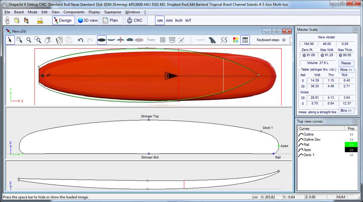
The image can then be resized and moved with the mouse. By pulling the side edges horizontally the image will keep its proportions.
And if you move the bottom or top edges vertically it will only change its width.
Press Shift to rotate the image.
The image can also be rotated from the Rotation window.
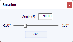
Press the space bar to hide the image.
All these function can be accessed through the contextual menu (Right-click).
Note that you need the Design option to load a ghost image.
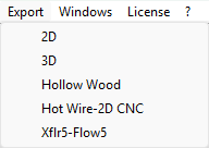
The Export menu allows exporting a model, or a piece of a model, in several formats.
Note that the 2D and Hollow wood exports need a Design Pro license to be used and the Export option is needed for 3D exports.
You can also do 2D and 3D exports without a license using Credits.
- Each definition curve of the Top view (Outline, Rail, Apex, Spin template, 3D layers outline...) can be exported as Projected on the XY plan,
or using Developped length (X using the length along the bottom stringer for bottom and top stringer for deck).
The width (Y) can also be exported as projected on the XY plan using the option Projected Width, or developped
along the deck or the bottom of the slices to get the developped surface using the options Developped Surf. from Bot and Developped Surf. from Deck.
For exemple, to export the developed surface of the deck of the board until the bottom rail curve, select "Rail" in the list of curves and check
the options Developped length and Developped Surf. from Deck.

These curves can be exported as Polylines in the .txt, .pdf, .dxf, .igs, or .vrl formats,
or Splines in the .pdf or .dxf formats for the Edited curves in Projected mode.
- The outline of the 3D layers and the plugs can be added to the Top view curves export.
- For Polylines a Margin can be added to the exported curve. It can be useful if you use the Profile export to cut an EPS blank with a hot wire and you need to add 1cm of foam on the deck and bottom for example.
- You can set a multiplication Factor of needed. With text, DXF and IGES you can change the export unit.
- The Side view curves can be exported as polylines with a side shift, and a tilt angle. It is then a section of the board along the length. If a rail shift is set instead, the exported curve is the profile taken at a fixed distance from the apex of the rail.

- One Slice allows exporting a slice at any X position.
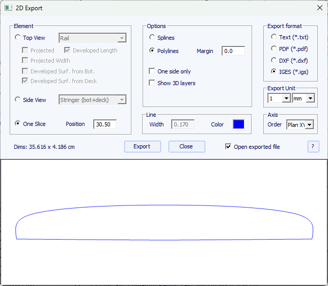
- By default the export Axis order is set to Plan XY. But for other formats than PDF is can be changed to XYZ, XZY, YZX... to change the orientation of the curves.
Note that you need a Design Pro license to export 2D curves.
- The 3D Export window allows exporting the Whole Board as Surface Meshes (in. dxf, .igs, . vrl, or .stl) or as Surface Splines (in .igs).

When exporting as Surface meshes you can modify the number
of slices and the number of points per slices (same as in the 3D
view).
The option Include Plugs will include the plugs holes in the export
(identical as the function "Convert plugs into 3D layers" of the Design mode).


When exporting a board as Surface splines , the exported
shape can be composed of several nurbs surfaces on each side, or one
surface per side.
You can change the Minimum distance between points as some softwares like Fusion 360 don't handle small surfaces well.
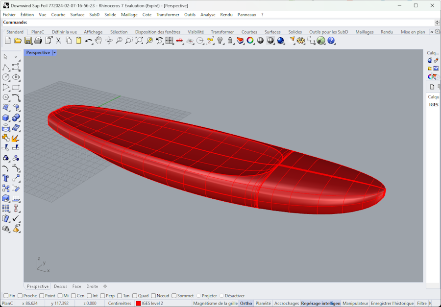
In both case, the conversion into Surface Splines goes through numerical adjustments which precision can vary depending on the shape.
- If Slices is selected you can set the number of exported slices, with Constant spacing or not.
Note that if you set the Number of slices identical to the number of definition slices, the export will keep the positions of the definition slices.

Note that you need the Export option to export your boards in 3D as meshes or spline surfaces.
- The Hollow Wood Plan export allows exporting a full size plan for building hollow wooden boards:
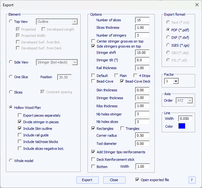
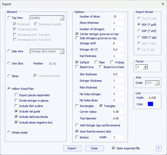
Stringers
You can set the number of stringers you want and define the side shift between 2 stringers. The stringers can even be tilted.
The connection notches with the slices can be placed on the top or bottom of the stringers.
The " Split stringer " option allows you to export the stringer(s),
and the rail if the Plain or Default rail mode are selected, in 2 to 6 pieces.
You can choose between 1 and 2 round connexion nodes, or one rectangular node.
The “ Add Stringer tips reinforcements ” option allows you to thicken the stringer at the notches if it becomes too thin.
Rail
There are four rail construction modes:
- Default corresponds to a wooden rail with holes at the slices positions. A notch is cut on the top and bottom of the rail of each slice.

- Plain corresponds to a wooden rail with no holes. The slices are cut vertical at the apex.

- 4 Stripes corresponds to a rail built with 4 identical stripes of square section

- Bead and Cove gives a squared notch on the bottom rail of the slices

- Bead and Cove deck gives a squared notch on the bottom rail and the deck rail of the slices

Slices
The " Custom slices spacing " option allows writing the list of exported slices x positions.
If this option is not used, then the Number of slices is defined in the Options group,
and the x positions of the slices are be evenly spaced.
Note that if you set the Number of slices identical to the number of definition slices,
the export will keep the positions of the definition slices.
The " Reinforcement stick " option allows adding a notch on the bottom or top to insert a reinforcement stick.
The width and depth of the notches must be defined.
Holes
The holes in the stringers and slices can be rectangular or triangular, with rounded corners.
Skin outline
The " Include Skin outline " option adds the half-outline to the plan.
It's thickness will be deduced from the stringers and the slices.
Additional Elements
The " Include rail guide " option adds guides to check the shape of the rails (full or square rail).
The positions are those of the exported slices limited to 5. So if you have 10 slices exported it'll correspond to one every two slices.
The " Include tail/nose blocks " option adds guides for the outline at the tail and the nose of the board.
The " Include slices negative bot. " option adds negatives of the bottom of each slice
to position them at the correct height. The width of each negative is the width of the Rail point of the slices if defined.
If there is no rail point defined, the width is equal the the width of the slice minus the defined "Rail thickness".
The " Export pieces serapately " option allows exporting each element in a separated file.
Toolpath
If the export format is G-Code, you can define the diameter of the tool used to cut the pieces
so that the radius is added to the contours, and a small slot will added to the corners to ensure a clean cut.
You can also choose a post-processor Format file as in the CNC mode,
and define the machine origin position and change the axes directions.
Export format
The export formats allowed for the Hollow wood plans are PDF, DXF, IGES and G-Code.
Note that you need a Design Pro license to export Hollow Wood plans.
The Hot wire-2D CNC path window allows creating and exporting a hot wire toolpath for cutting the profile or the outline of one or several models.
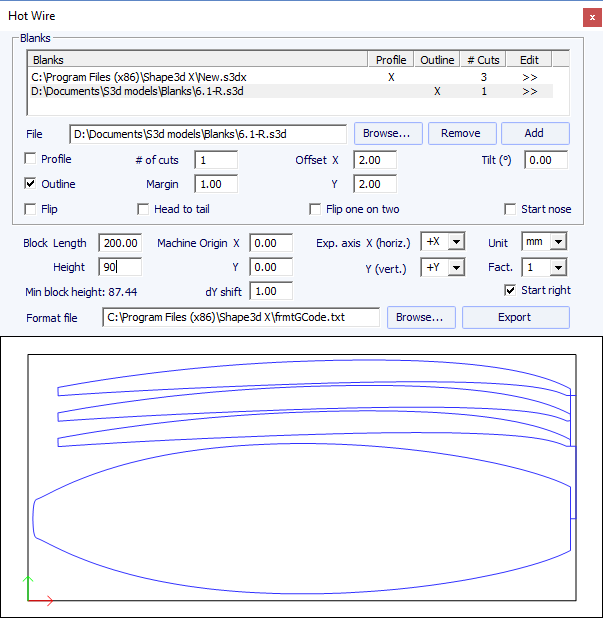
Each profile/outline can be duplicated, shifted and tilted separately.
- "Margin" set the additional thickness around the original shape
- "Tilt" set the tilt angle of the profiles/outlines in degrees
- "Flip" flips the profile upsidedown
- "Start nose" starts the cut at the nose of the board
- "Offset X Y" set the shift of the profiles/outlines relatively to the previous position
- "# of Col." defines the number of times you want to duplicate the profile/outline side by side
- "# of Rows" defines the number of times you want to duplicate the profile/outline on top of each other
- "Head to tail" reverse nose and tail every two row or column
- "Flip 1/2" flip every two row or column
- "dX flip" and "dY flip" is the shift between two flipped profiles/outlines
- Bloc Length and Height, or Plank Length, Width and Height defines the size of the foam block or plank to be cut
- "Machine Origin X Y" defines the zero of the machine relatively to the top left corner of the block
- "Exp. axis" defines the axis and their directions
- "Unit" defines the export unit
- "Fact." is a multiplication factor for the export
- As for the CNC cutting, the "Format file" contains the header and the footer of the G-Code cutting files.
Amongst other commands, the header can contain the cutting speed command.
This window also allows exporting G-Code cutting files to cut 2D pieces like stringers in a wood plank
or board or 3D layers surfaces in a PVC sheet.
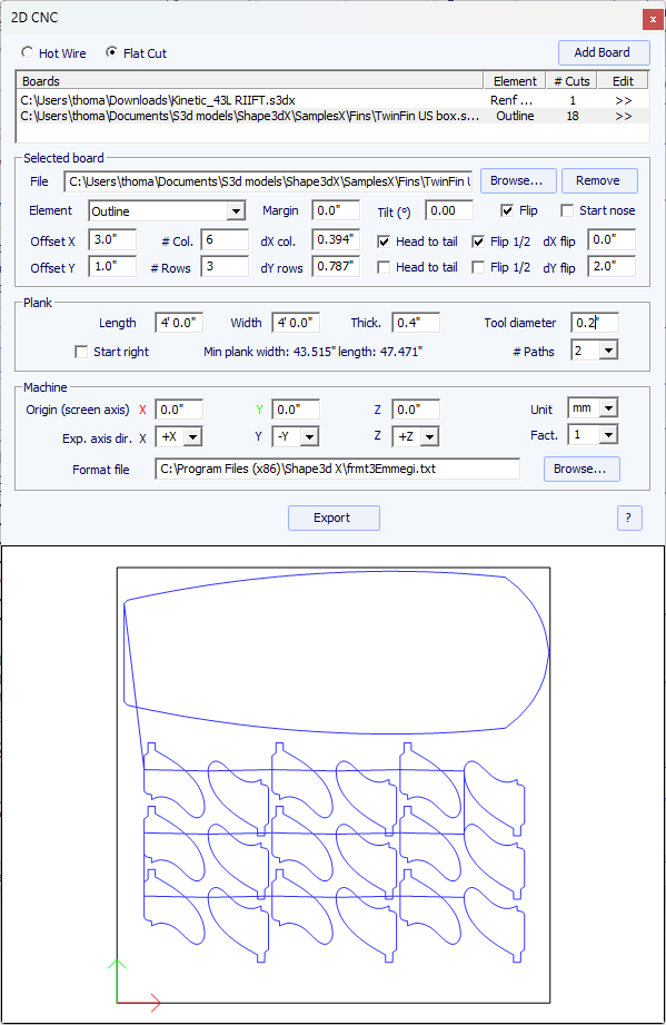
When Flat Cut is selected, then you can define the tool diameter, the thickness of the plank,
and set the number of paths you want to do. If you set 2 paths for exemple, the first path will cut half of the thickness of the plank,
and the second path the whole thickness.
The option "Xflr5-Flow5" opens the Export dialog box for the Xflr5 or Flow5 softwares, that allow computing the lift and the drag of an hydrofoil (check the dedicated FAQ).
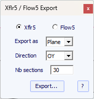
The menu "Windows", allows choosing the screen settings.
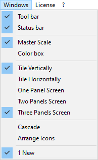
The top Tool bar and the bottom Status bar can be displayed or hidden.
The Master Scale , the Color box and the Smart Functions can be opened from here.
The options "Align Master Scale Right, Left, Top and Bottom" allows placing the
Master Scale and the other tool windows where you want in the screen.
The design window can display 1, 2 or 3 panels.
The option "Compare Boards" allows you to view all open files side by side for comparison.

The menu License allows you registering your license, whether Shape3d has access to the Internet or not.
See menu Register your License for more details.
- The menu items Add a Seat to Current License, Add an Option
and My Account open your Internet browser to let you do these actions on the Shape3d.com website.
You can also open the Shape3d Cloud directly from there.
The menu "?", gives access to the online help (this manual plus the videos and FAQ, and the Warehouse where you can download many samples) and the version information.
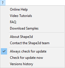
- About Shape3d will give you the information about the version of Shape3d you're using, your license, and also the fingerprint of your computer:
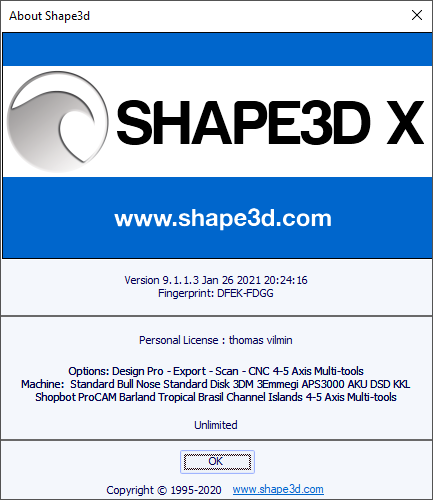
- Contact the Shape3d team allows you to send a message to the Shape3d team:
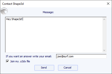
- In this menu you can also check the option Always check for update, so that you'll always know if there's a newer version if you're connected to the Internet. When an update is available, the following window will pop up at the opening of Shape3d, that lets you download the new version of Shape3d:
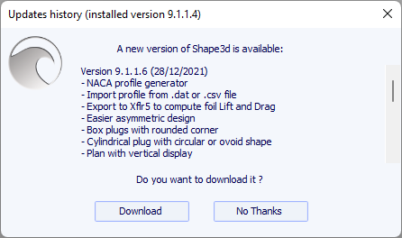
- You can also Check for update now.
- Finally, if you're connected to the Internet, you can check the Versions history that will redirect you to our website on the page UpdatesHistory.aspx that gives you the list of improvements that have been done on each version of Shape3d X.
The context menu appears when you right-click inside a panel.
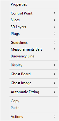
It contains almost all the features of the menu bar, and allows using them quicker.
Note that by pressing the Shift key, the right-click will directly open the appropriate context submenu. For example Shift + right-click when the Slices panel is selected directly opens the Slices submenu, or the Control Point submenu if a control point is selected.
The Left Click
The left click allows selecting a control point, a guideline, a fin plug or a logo.
The Ctrl + Left Click
Ctrl + left click allow selecting several points, guidelines or fin plugs.
The Shift + Left Click
Shift + left click allow selecting all the points, or guidelines, between two selections.
Shift + Ctrl + left click will select a control point in priority even if a guideline is displayed at the same position.
The Double Left Click
The double left click allows adding a control point or a guideline if the guidelines are shown on screen.
The Right Click
The right click makes the context menu appear.
The Shift + Right Click
Shift + Right click directly open the appropriate context submenu.
The Tab key
The Del key
Del will delete the selection.
The Ctrl + C keys
Ctrl + C copy the curve (outline, bottom, deck, thickness, or slice) in the clip-board. Then, you can past this curve on another board, or on another slice if the curve is a slice. Note that if you select one control point of the copied curve, and then one point of the other curve, it will copy-paste the whole curve. But you can also copy-paste just a section of curve by selecting the control points you want (press the Shift or Control keys while selecting the points). See The Tool Bar.
The Ctrl + V keys
Ctrl + V Paste the copied curve on the selected curve. See Ctrl + C and The Tool Bar.
The Ctrl + A keys
Ctrl + A selects all the points or all the guidelines.
The Ctrl + Z keys
Ctrl + Z call the Undo.
The Shift + Ctrl + Z keys
Shift + Ctrl + Z call the Redo.
The Ctrl + N keys
Ctrl + N open the New board window.
The Ctrl + O keys
Ctrl + O open the board files browser.
The Ctrl + S keys
Ctrl + S save the modifications.
The Ctrl + R keys
Ctrl + R save the modifications and load the actual shape as the reference shape.
The Ctrl + B keys
Ctrl + B switch from one board to another if several boards are open at the same time.
The 1, 2, 3, 4... keys
The numbers allow you to switch between views in Design mode, orientation in 3D and CNC mode, or plan view in Plan mode.
Ctrl + 1, 2, 3, or 4 opens Design, 3D, Plan, or CNC mode.
The F key
F allows you to switch to a vertical display in Design mode, or to flip the board in 3D and CNC mode.
The H key
H hides all the points to let a clean curve.
The T key
T shows the tangents of all the control points of all the displayed curves.
The D key
D shows the depth of the selected curve arc, and the distance and angle between the two control points.
The E key
E shows the design errors (superposed control points in green, kinks and loops in red) of all the displayed curves.
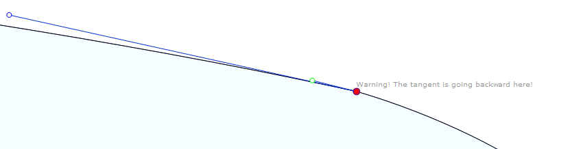
A Shape3d model must always have a strictly positive width and thickness, in particular at the tail and nose!
- It means that the tail and nose of the outline must be "squared" rather than "pined".
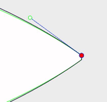
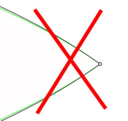
- In the same way, the stringer must begin and end with a positive thickness.
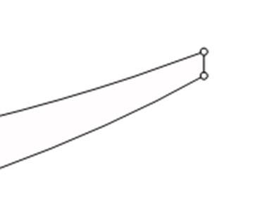
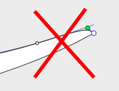
A tail and nose with a positive width and thickness will allow you to avoid mistakes due to the fact that you can't see the slices defined at the very tail and nose.
All the design curves must lie between x = 0 and x = length. Any loop would be misinterpreted by the software.
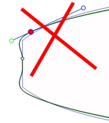
Check the smoothness of the curves.
- A general rule would be: the less control points the smoother.
- Prefer continuous tangents
![]() to angulous tangents
to angulous tangents
![]() .
The curves must not do any loop.
.
The curves must not do any loop.
- Avoid zero length tangents because it could do a very small loop around the control point.
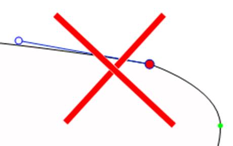
- Check that you didn't insert two control points at the same place
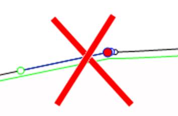
You can use the E key shortcut that will show the superposed control points in GREEN, kinks and loops in RED.
- Here again, the less slices the smoother. The right number obviously depends on the shape...
If you design a new model, a good way to get a smooth shape is to
begin with the design of the center slice, and then make all the
other slices from this one. For that you can use the copy-past
facility: select a slice on the outline view, click on the copy
button ![]() in the toolbar, select another
slice and press the paste button
in the toolbar, select another
slice and press the paste button ![]() . Modify these slices to make
the shape smoothly evolve from the tail to the nose.
. Modify these slices to make
the shape smoothly evolve from the tail to the nose.
- The design of a slice usually needs 4 to 5 control points.
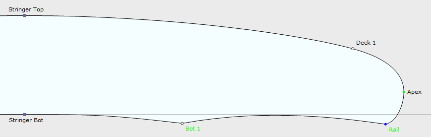
- It is safe to define the apex point (GREEN
![]() , with a vertical tangent
, with a vertical tangent
![]() ),
the rail point (BLUE
),
the rail point (BLUE
![]() , with an angulous tangent
, with an angulous tangent
![]() ),
and possibly another point on the deck to have a better control of the rail shape. The deck center point
generally has a horizontal tangent
),
and possibly another point on the deck to have a better control of the rail shape. The deck center point
generally has a horizontal tangent ![]() . Same for the bottom
center point except in case of V or inverted-V.
. Same for the bottom
center point except in case of V or inverted-V.
- It is important to check that two slices are not placed at the same x position. For that you can use the list of slices that appears when you are designing a slice. This list shows each slice with its x position.
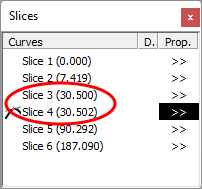
- Concerning the apex point definition, you have two choices: either you fix a point at the widest position that you set as the Apex point, or you don't define an apex point.
Note that defining the Apex point assures that the separation between the deck and the bottom cut in the CNC mode will be clean. In particular, if the edges of some slices are vertical, the detection of the widest point can either give the top or the bottom of the vertical section, and end up with a waterline that jumps from the top to the bottom of the vertical section.
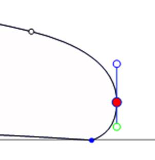
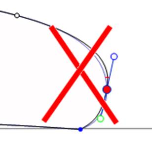
If you define the Apex point, make sure it is the widest point on each slice, or it will give inconsistent toolpaths in the CNC mode.
- It is also important to define the Rail point, as it will
assure a clean cut of the tuck of the rail. It will also allow you
to define the number of paths you want between the stringer and the
rail, and between the rail and the apex.
The Rail is also used for the option "Map on extended rail" of the 3D layers.
Note that you can define a Rail point on the bottom of the slices (below the Apex point) and one on the deck.

![]() Zoom
in and out
Zoom
in and out
You can choose the Moving/Zoom option or the related button of the tool bar, and then, click with the right button in the area to zoom in or with the left button to zoom out.
![]() Window
zoom
Window
zoom
In that mode, if you draw a rectangle with the mouse, the view is enlarged and the contents of the rectangle are fitted to the pane view. A right click zooms back.
![]() Move
Move
Move the drawing with the mouse.
![]() Rotate
Rotate
To make the board rotate, you have to select the option Moving/Rotate, and hold the left button down somewhere in the window while moving the cursor.
![]() Spot
light
Spot
light
To move the spot light, press the left button somewhere in the window, then move the cursor to place the spot light where you want.
These features are accessible through the menu "Mode".
![]() Points
of view
Points
of view
Choose the point of view: top, bottom, side, nose, tail, perspective... or vertical.
These features are accessible through the menu "View".
![]() Flip
the board.
Flip
the board.
![]() 360 Deg
rotation of the board.
360 Deg
rotation of the board.
![]() Create a 3D web viewer for the Shape3d Warehouse.
Create a 3D web viewer for the Shape3d Warehouse.
![]() Display the board as wire (Design option needed). _Toc454958725_1
Display the board as wire (Design option needed). _Toc454958725_1
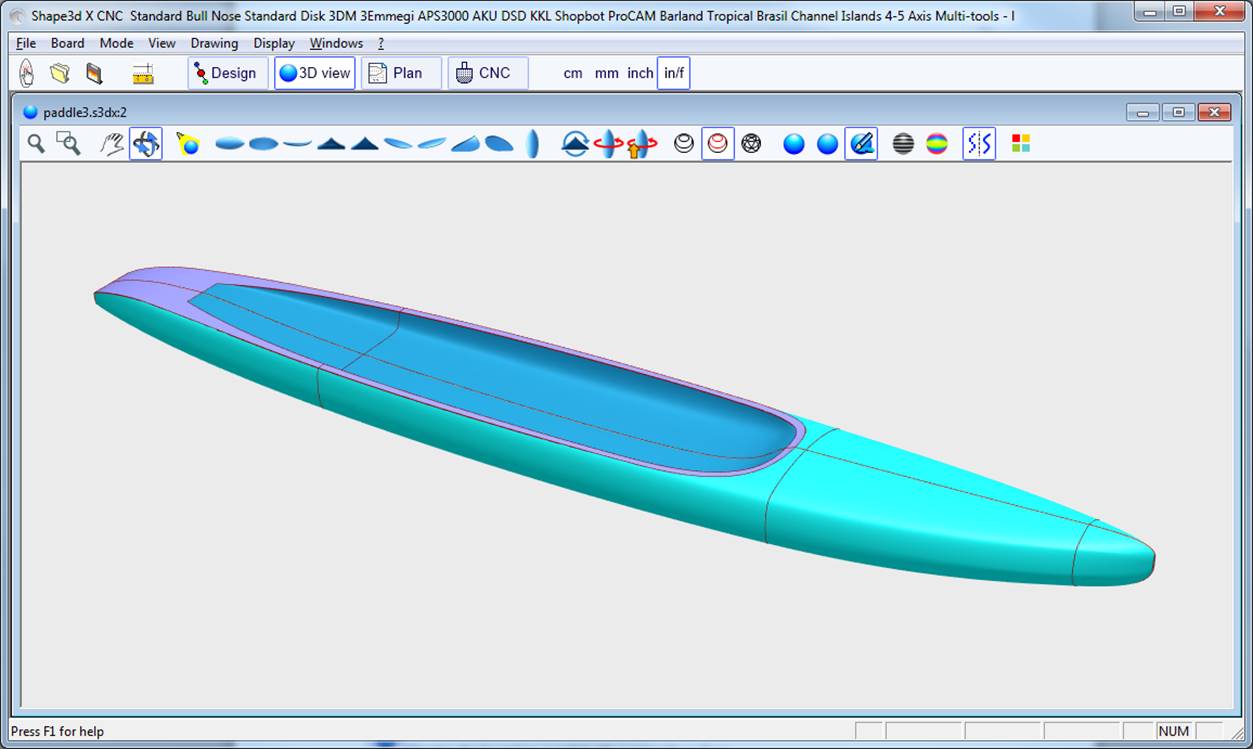
![]() Display definition curves (ie the curves that connect the control points of the slices), the outline of the 3D layers, and the slices (Design option needed).
The definition curves can be limited to the angulous control points of the slices (see The 3D Properties Box).
Display definition curves (ie the curves that connect the control points of the slices), the outline of the 3D layers, and the slices (Design option needed).
The definition curves can be limited to the angulous control points of the slices (see The 3D Properties Box).
![]() Display the meshes of the board (Design option needed).
Display the meshes of the board (Design option needed).
These features are accessible through the menu Elements. They can be cumulated to obtain a solid view with a wire frame. The number of intermediate slices corresponds to the number of meshes along the length of the board. The number of surface lines corresponds to the number of meshes along the width of the board.
![]() Display the board as a solid with a smooth surface.
Display the board as a solid with a smooth surface.
![]() Add reflections from a list of reflection maps. See "Properties
Box" (Design option needed).
Add reflections from a list of reflection maps. See "Properties
Box" (Design option needed).
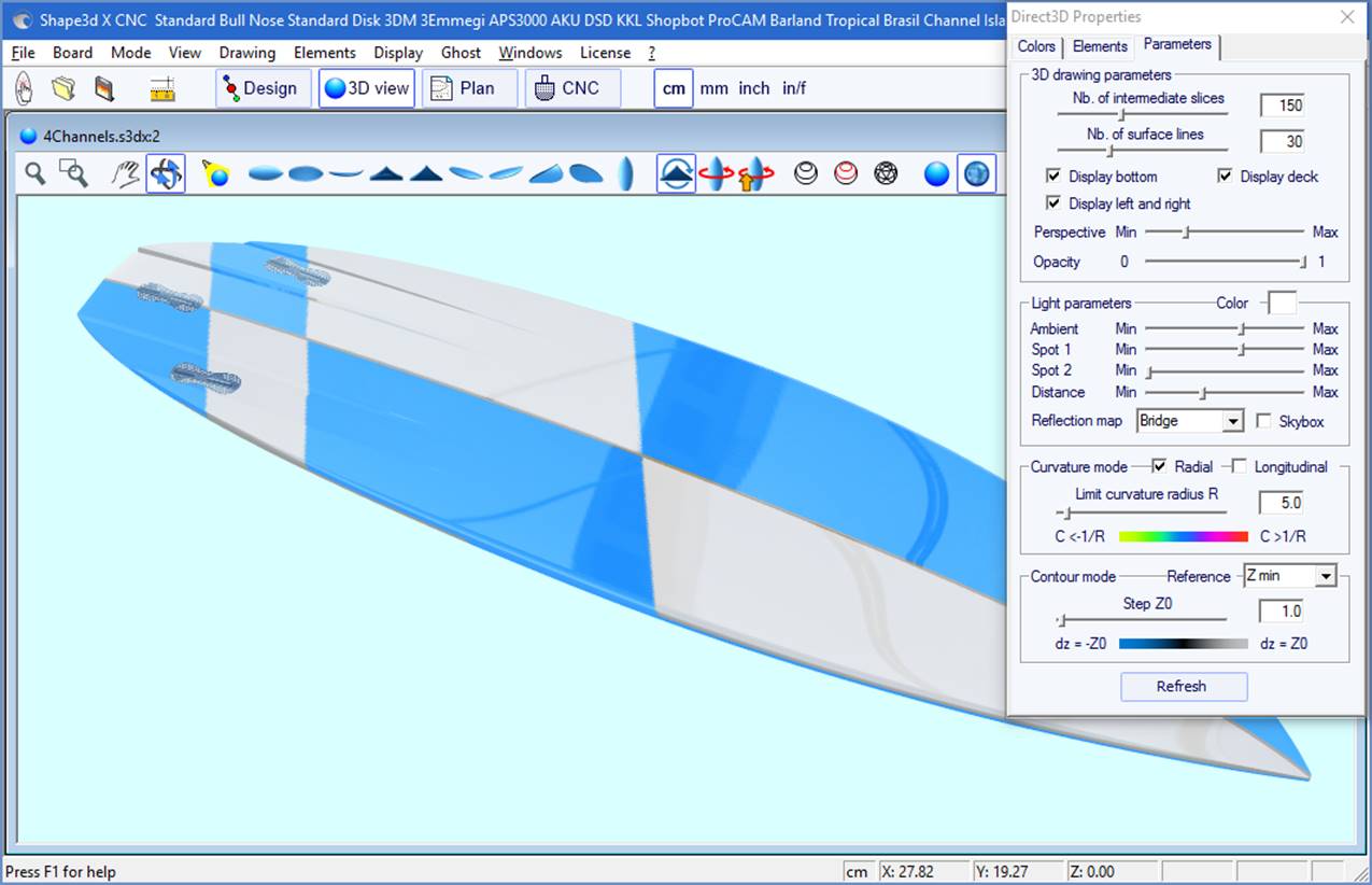
![]() Display grey lines with fixed height steps, relatively to a defined position (Pro option needed).
The "Solid lines" option gives solid level lines instead of grey gradients.
Display grey lines with fixed height steps, relatively to a defined position (Pro option needed).
The "Solid lines" option gives solid level lines instead of grey gradients.
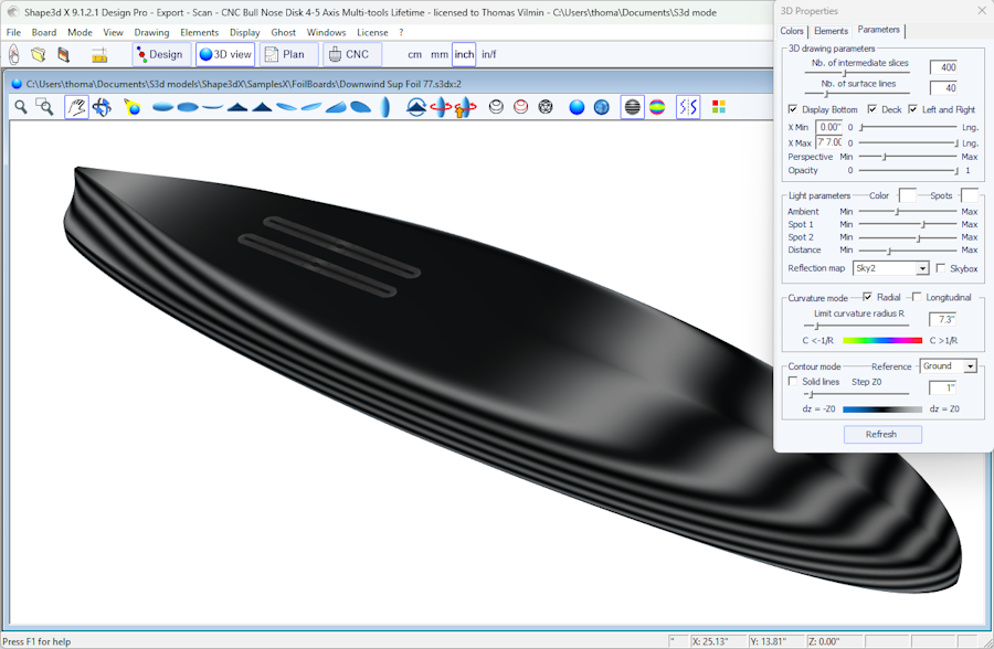
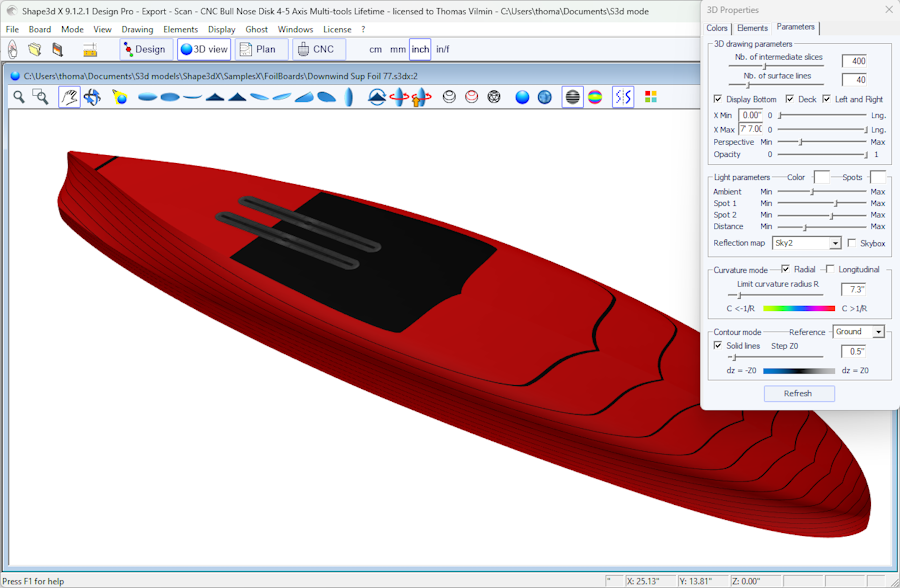
![]() Display the curvature (radial and/or longitudinal) with colors (Pro option needed).
Display the curvature (radial and/or longitudinal) with colors (Pro option needed).
Radial
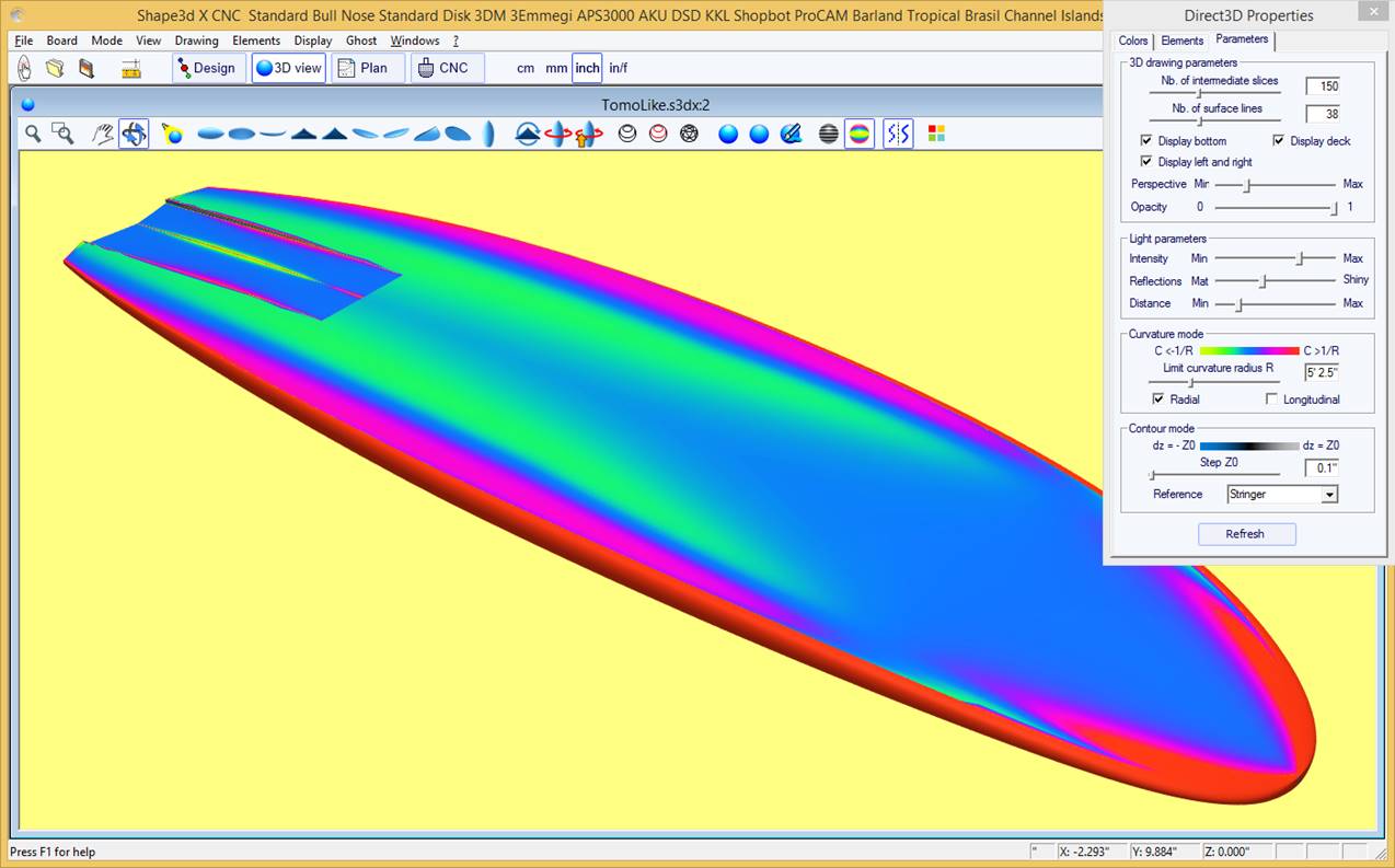
Longitudinal
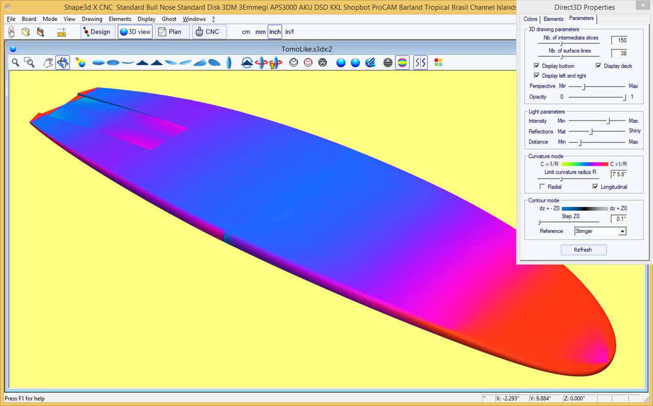
The highly convex areas will be displayed in green and yellow, and the highly concave areas will be displayed in pink and red. The blue areas are almost flat. The relative curvature radius R can be adjusted to show the curvature (C = 1/R) changes more effectively.
![]() The 3D Properties Box
The 3D Properties Box
The "3D Properties" window allows changing the colors, the decoration, and the definition of the 3D drawing.
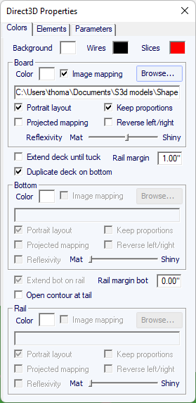
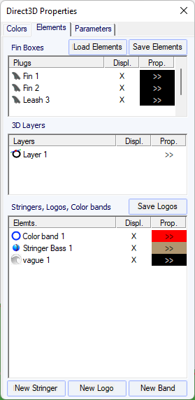
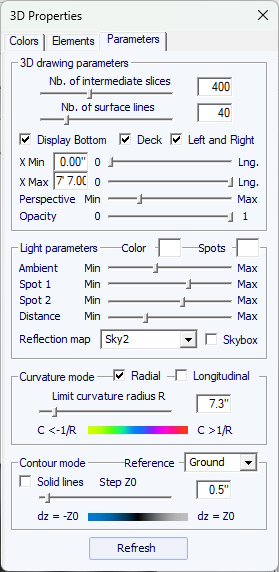
The 3D mode allows mapping images on the board. The mapping on the deck can stop at the apex, or the rail, or at a defined distance from the apex. The mapping can be duplicated on the bottom, or another image can be mapped on the bottom. This gives a very realistic idea of how your board will look like at the end.
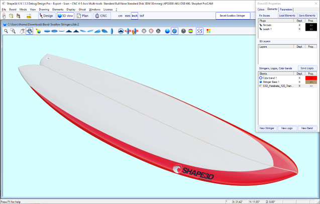
The Plugs can be displayed. For most of the standard systems you can choose the color.
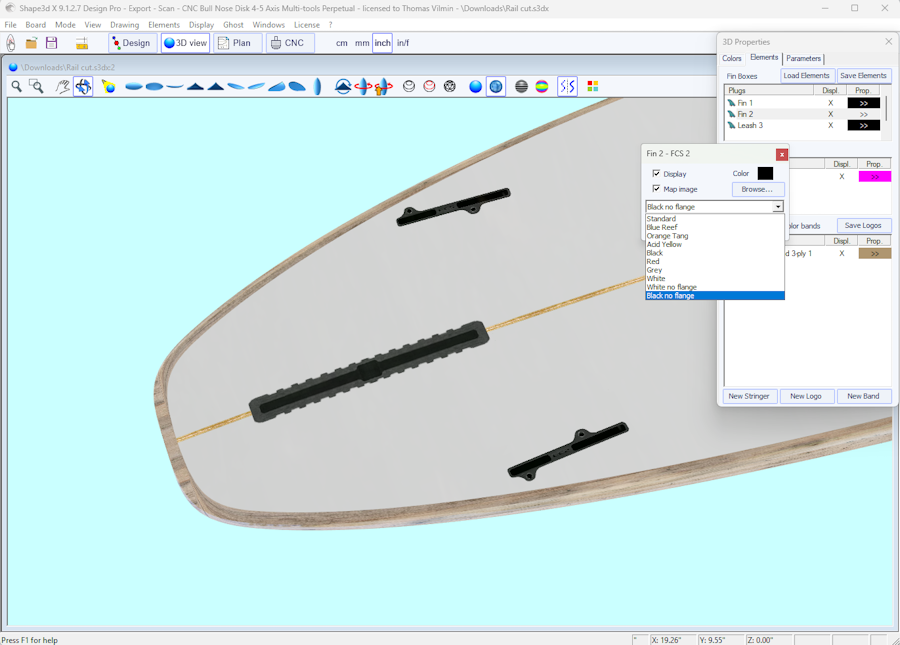
The 3D layers can be displayed in a different color than the board, or with a different texture.
You can also display the original surface of the board before the 3D layer was added (surface before).
The 3D layer can be displayed on a limited range of x, between X Min and X Max.
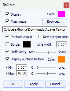
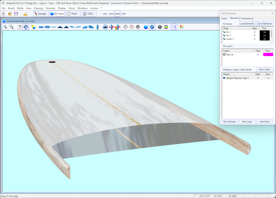
You can add Color Bands to the board. The color bands can be straight bands or bands that follow the outline of the board, like a pin line. It can also contain color gradient.
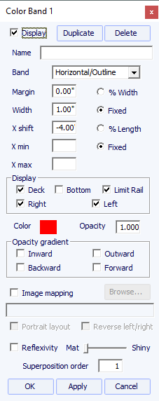
You can add multiple Logo images. The logos can be moved and resized, and mapped in different ways on the board.
![]()
You can also add Stringers. The stringers can be shifed and tilted. You can set its color or choose a type of wood.
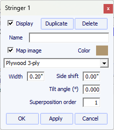
Note that you need the Design option to add logos or color bands.
The functionalities displayed in the menu are the same as the ones presented in the section "Toolbar".
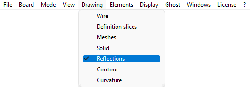

 General view of the board
The general plan allows you to print (on paper or in a PDF) technical sheets containing a top view, and/or a bottom view,
and/or a side view, or a section view at a given X position.
You can save as many plans as you want and switch between them using the "Select Plan" drop-down list.
Default dimensions are displayed at 3", 6", 12", 18" and 24" from the tail and nose
(or 5,10, 20, 30 and 50 cm from the ends, if the unit is centimeter or millimeter).
But the "Measurements const. spacing" option allows you to display measurements with constant X spacing.
You can also choose to display the Measurement bars instead.
These views are customizable. You can display or hide each curve or element such as 3D layers, plugs, or logos.
The Plan Parameters window contains the Zoom buttons
which allow you to enlarge or reduce the size of the design in the plan, and the size of the displayed page.
The page size and line thickness can be changed.
A correction coefficient for the display size and full-size printing can be defined:
In full scale mode, the rendered size can be too small or too big depending on your screen or printer settings.
If too big, set the factor smaller than 1. Set the factor larger than one if too small.
For exemple if the displayed width is 21 instead of 20, the factor is 20/21 = 0.95.
If the displayed width is 20 instead of 21, the factor is 21/20 = 1.05.
The "CSV export template" is the address of the template file that you can use for the CSV export
in the Plan mode and the "File Selector".
The template can just contain ALL; and then all the possible data will be exported in the CSV.
Or it can contain only the list of columns you want, like for exemple:
LENGTH_IN;WIDTH_IN;THICKNESS_IN;VOLUME
or more:
NAME;LENGTH_IN;WIDTH_IN;THICKNESS_IN;VOLUME;LENGTH_CM;WIDTH_CM;THICKNESS_CM;WIDTH_TAIL_12_CM;WIDTH_TAIL_3_IN;
WIDTH_NOSE_12_CM;WIDTH_NOSE_3_IN;ROCKER_TAIL_CM;ROCKER_NOSE_CM;GRAVITY_CENTER_X_CM;PROJECTED_SURFACE_CM2;FIN_CENTER_X_TAIL_CM;
FIN_SIDE_X_TAIL_CM;FIN_SIDE_Y_RAIL_CM;FIN_SIDE_TILT_DEG;LEASH_X_TAIL_CM;LEASH_Y_CENTER_CM
_IN in LENGTH_IN indicates that we want the length in inches; _CM in centimeters. _TAIL_12_CM indicates that we want a measurement 12cm from the back.
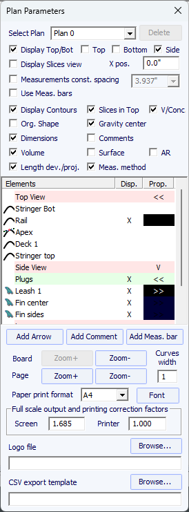
For each element a label that can be moved with the mouse can be displayed, as well as the distance to the tail, nose, center or rail.
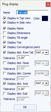
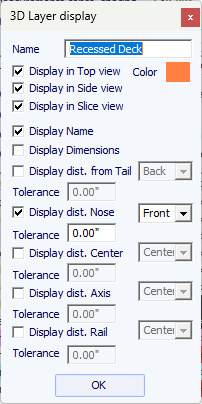
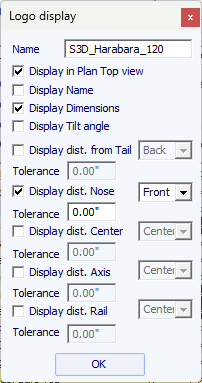
The general plan can be displayed horizontally or vertically  .
.
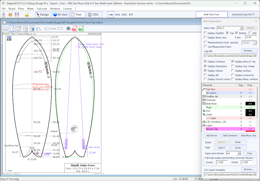
Comments and arrows can be added and placed with the mouse. Font and color are editable.
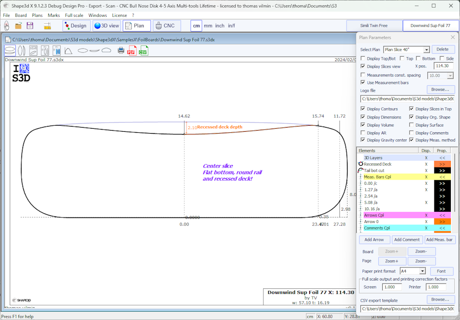
 Board Chart
Displays the general information on the board, plus 3D wire views.
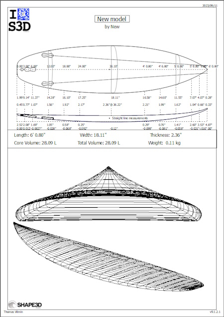

 Order Sheet
Displays the general information on the board with either the plan in vertical mode, or a deck and bottom view from the 3D mode.
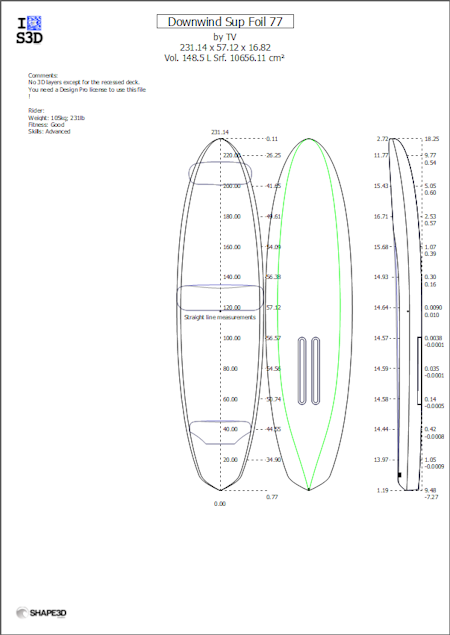
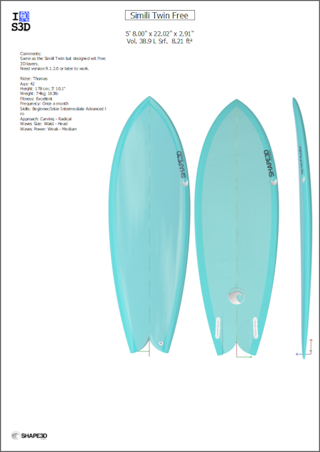
The print sheets can be used with the free Lite version of Shape3dx.
![]() Volume and Surface distribution curve
Volume and Surface distribution curve
Displays the volume and projected surface distribution along the X axis. It also shows the ID Numbers of the board (see Display Menu of the Design mode).
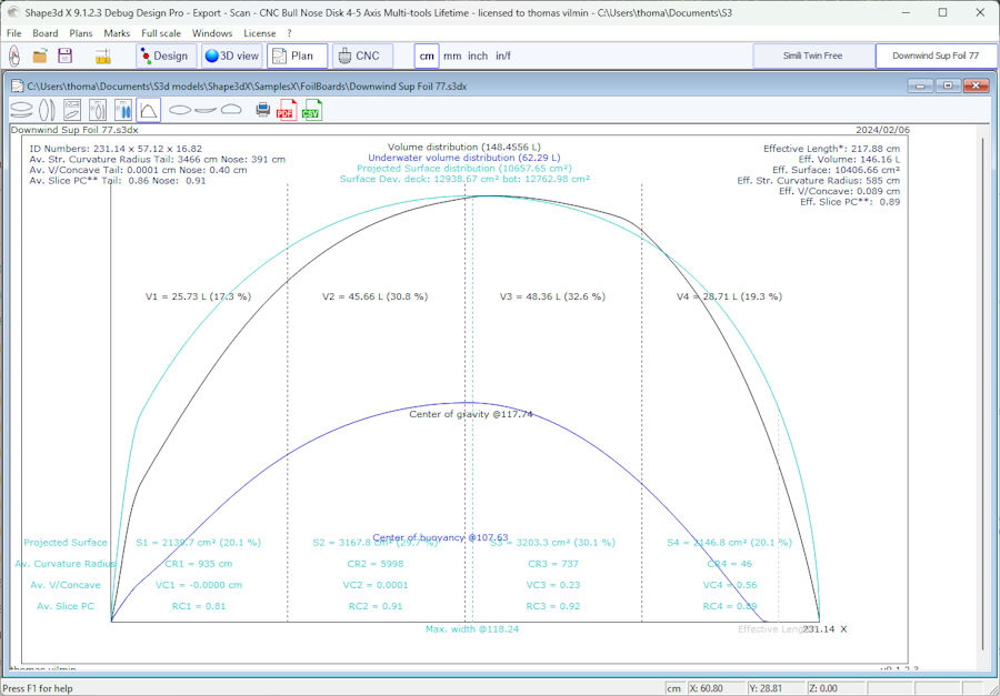
![]() Full scale views
Full scale views
Allows full scale prints of the Outline, Stringer, Profile, Slices, developed surfaces and Spin Template on a regular printer (on several pages).
Note that Volume distribution and Full scale views need the Design option to be used.
You can also make these 1:1 scale prints without a license using Credits.
![]() Printing the displayed plan
Printing the displayed plan
![]() Export of the displayed plan in PDF format
Export of the displayed plan in PDF format
![]() Export to a spreadsheet
Export to a spreadsheet
Exports to CSV/Microsoft Excel format. For the general plan, the CSV export contains the main measurements of the board.
If a CSV export template is defined then you can choose which data you want to export.
![]() Opens the Plan properties window
Opens the Plan properties window
These features are accessible through the menu "Plans".
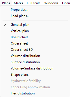
The "Plans" menu lead to the different views that are displayed in the toolbar.
"Load plans..." allows loading multiple plan configurations from another s3dx file.
The "Hydrostatic Stability" shows the evolution of the Metacenter height with underwater volume, and also the evolution of the Righting arm with heel angle.
Basically, if the Metacente is lower than the center of gravity of the rider it means that it is not self-stable: the rider needs balance not to fall down.
On the other hand if the Metacente is higher than the center of gravity of the rider it means that the rider can be a beginner and not fall down.
The higher the Metacente the more stable the board.
The Righting arm represents the stability strength: the higher up it goes the more stable the board. It usually reaches a maximum at special heel angle. For higher heel angles the board will flip.
This menu allows comparing the lateral stability of two boards with the Ghost function.
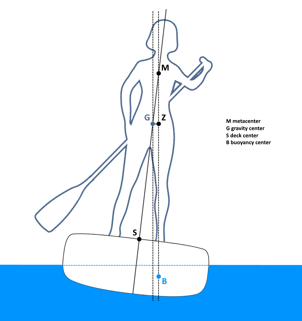
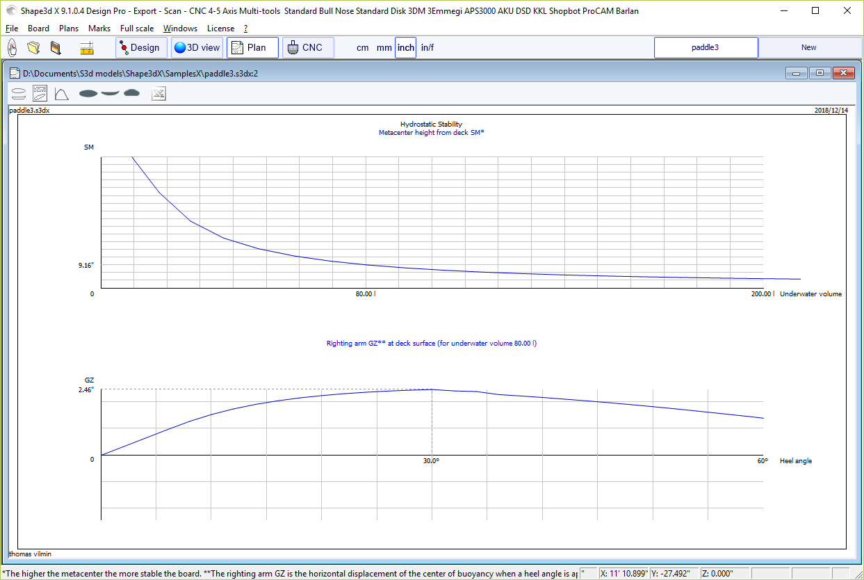
The "KAPER Drag approximation" gives the evolution of the viscous drag and the residual (wave) drag with speed. The residual drag is given by the KAPER APPROXIMATION formula based on tests on sea kayaks. This curve can be far from the truth, consider it with caution. It can be usefull to compare two SUPs though.
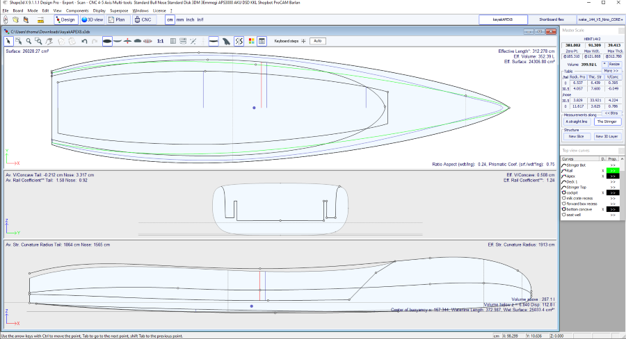
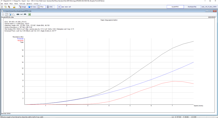
See references:
http://www.marinerkayaks.com/downloads.htm
http://www.oneoceankayaks.com/smhydro/hydro.htm
The "Flex distribution" gives the flex modulus (elastic modulus * quadratic momentum) of the sections of the board along its length.
We use the Beam theory approximation to evaluate the flex of the board.
The density and the Elastic modulus of the core must be given.
The composite construction must be defined using 3D layers. For example the fiber glass can be defined using a "Constant depth" 3D layer
(with positive or negative depth, as you want), for which you give the density and elastic modulus. Several layers with different dentity and elastic modulus can be superimposed.
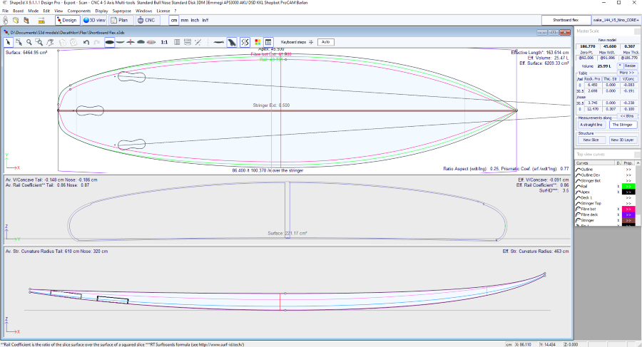
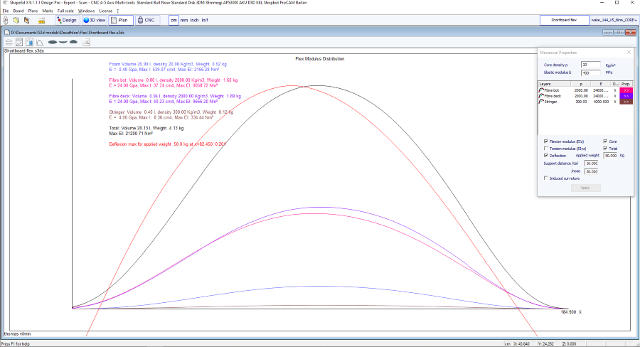
See references:
https://en.wikipedia.org/wiki/Euler%E2%80%93Bernoulli_beam_theory
Note that Hydrostatic Stability, KAPER Drag approximation, and Flex distribution need the Pro option to be used.
The menu "Marks" gives access to the lists of measurements of the outline, profile and slices.
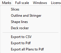
The coordinate axis is classically defined with the X-axis as the longitudinalaxis, the Y-axis as the transversalaxis, and the Z-axis as the verticalaxis.
Outline and stringer: Provide the marks needed for creating the design. The meaning of the column is as follow:
X-Coordinate: Position on the longitudinal axis.
X-Developed: Position of marks on the board, taking into account its curve (Essential to draw the marks on the foam loaf after cutting).
Hull-Z: Height of the bottom compared to 0.
+sdw: Z height minus the thickness of the sandwich (defined in Board/Properties).
Deck: Z height of the deck compared to the point z = 0.
-sdw: Height of the deck minus the sandwich thickness.
Outline: Width Y at X.
-sdw: Width minus the sandwich thickness.
Carre: Width Y of the edge point.
-sdw: Edge width (taking into account the sandwich, see Plan/Slices full size to visualize this position).
Slices: The marks of a given slice.
Shape lines: Marks of the shape lines. See screen Plan/Shape plans 1 and 2 to understand the meaning of the columns.
The point is to draw the S1 and S2 shape plans lines first, and cut the plans.
Then you can draw the A1 and A2 plans lines, and cut the secondary plans to get closer to the final shape.
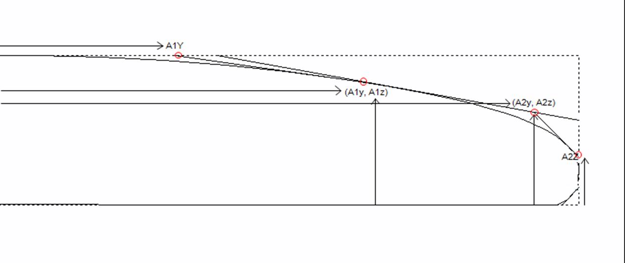
This menu also allows accessing the CSV export and print to Pdf functions. If several plan configurations are defined you can export all in one Pdf.
The menu "Full Scale" gives access to full scale views of the Outline, Stringer, Profile, Slices, developed surfaces and Spin Template,
and allows printing them with a regular printer (on several pages).
The developped surface can be the one of the deck or the bottom, and the limit curve can either be the Apex or the Rail curve.
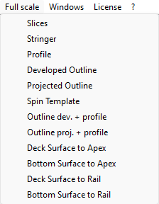
The CNC mode allows loading the blank or foam block in the CNC machine environment, compute the toolpath for a bull nose (3 to 5 axis) or disk cutter,
and export it in the G-Code or DXF format.
It is accessible with a Design Pro license, but you need the CNC option to export the tool path.
You can also export toolpaths without a license using Credits.
The machine file is the file that contains the default settings used in the CNC mode of Shape3d.
After the installation of Shape3d, the default Machine file will be placed in the Shape3d.exe folder. We recommend you move it to a new directory so that it is not replaced by the default version if you install an update of Shape3d. It is very important to keep this file in a safe folder, and to do a backup, since it contains all the default settings corresponding to your machine. If ever these settings are modified by mistake, you can get you settings back reloading the backup machine file.
If you open a new board file that hasn't been used in the CNC mode, the CNC parameters will be loaded from the machine file, and the complete location of the machine file will appear in the title of the CNC properties window.
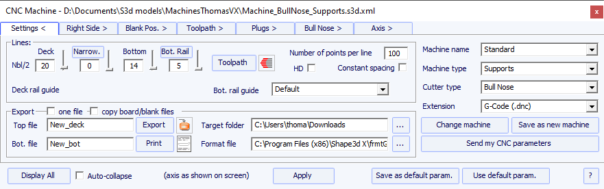
If the board file already contains some CNC parameters, the parameters can be loaded from the board file (if the option Load CNC parameters from board files is checked in the preferences), and the CNC properties window will have the title "Parameters from board file".
The machine file can be changed in the CNC properties window clicking on the button "Change machine file".
It can also be changed directly in the Preferences window. The Preferences dialog box can be opened through the menu "File", "Preferences...":
The "Format File" is the post processor file that contains the header and the footer of the G-Code cutting files that will be exported.
It is a text file that can easily be modified. It needs to be adapted to each machine!
After the installation of Shape3d, the default Format file will be placed in the Shape3d.exe folder.
We recommend you move it to a new directory so that it is not replaced by the default version if you install an update of Shape3d.
It is very important to keep this file in a safe folder, and to do a backup.
We recommend you save this file in the same folder as the Machine file.
Then select it in the Settings tab of the Properties window.
Here is an example of G-Code format
The tags between $$ will be replaced by the corresponding values, and ❬COORDINATES❭ by the cutting positions:
You can use the tags $DECK_TAIL_0.0$ $DECK_NOSE_0.0$
$BOT_TAIL_0.0$ $BOT_NOSE_0.0$ with any distance from tail or
nose to get the height of the deck or bottom stringer
(along a straight line, in the unit used in the CNC mode of Shape3d).
$STRUT_TAIL_0.0$ $STRUT_NOSE_0.0$ will give you the
blank bottom height during deck cut, and the board deck height
during bottom cut.
Here is the list of all the usable tags:
❬BOT_HEADER❭❬/BOT_HEADER❭ special bottom header area
❬DECK_HEADER❭❬/DECK_HEADER❭ special deck header area
❬BOT_FOOTER❭❬/BOT_FOOTER❭ special bottom footer area
❬DECK_FOOTER❭❬/DECK_FOOTER❭ special deck footer area
❬BEFORE_CHANGE_SIDE❭❬/BEFORE_CHANGE_SIDE❭ command before changing sides (left-right)
❬AFTER_CHANGE_SIDE❭❬/AFTER_CHANGE_SIDE❭ command after changing sides (left-right)
$MODEL_NAME$ surf_.Nom()
$SIDE$ "Deck" or "Bot"
$DATE$ CTime::GetCurrentTime()
$MCU_CUTTER_TYPE$ "MCUTOOL T1 D%.2f R%.2f F%.2f L%.2f C1"
$DIMENSIONS$ dims
$DIMENSIONS_CM$ dims in centimeters
$DIMENSIONS_MM$ dims in millimeters
$DIMENSIONS_INCH$ dims in inches
$DIMENSIONS_INF$ dims in fractional inches
$VOLUME$ vol
$H1_H2$ "H1 : x, z H2 : x, z", also available $H1_H2_CM$, $H1_H2_MM$, $H1_H2_INCH$, $H1_H2_INF$
$H1_X_ZERO$, $H2_X_ZERO$ H1 or H2 x from machine origin, also available in CM, MM, INCH, INF
$H1_X_TAIL$, $H2_X_TAIL$ H1 or H2 x from blank tail, also available in CM, MM, INCH, INF
$H1_X_NOSE$, $H2_X_NOSE$ H1 or H2 x from blank nose, also available in CM, MM, INCH, INF
$H1_Z$, $H2_Z$ H1 or H2 z from the ground, also available in CM, MM, INCH, INF
$H1_Z_ZERO$, $H2_Z_ZERO$ H1 or H2 z from machine origin, also available in CM, MM, INCH, INF
$TAIL_STOP_X_ZERO$, $TAIL_STOP_Z_ZERO$ the x and z of the tail block (at the height of the middle of the tail) from machine origin
$NOSE_STOP_X_ZERO$, $NOSE_STOP_Z_ZERO$ the x and z of the nose block (at the height of the middle of the nose) from machine origin
$MACHINE_FILE$ machine file name
$BLANK_FILE$ blank file name
$OFFSET_BRD_BLANK$ X Y Z distances between the board and the blank tails
$TILT_BRD_BLANK$ Tilt angle of the board in the blank
$DIST_BOARD_BLANK_TAIL$ Distance Board-Blank tail
$DIST_BOARD_BLANK_NOSE$ Distance Board-Blank nose
// Distances from BOARD tail or nose
$X_CENTER$ gives the x position of the board center from zero
$X_FROM_TAIL_x.x$ gives the x position form zero of a point at the distance x.x from board tail
$X_FROM_NOSE_x.x$ gives the x position form zero of a point at the distance x.x from board nose
// Deck board stringer Z
$TAIL$ "TAIL : %.2f, %.2f" Board tail X Z position
$NOSE$ "NOSE : %.2f, %.2f" Board nose X Z position
$DECK_CENTER$ Z position of the stringer deck curve center
$BOT_CENTER$ Z position of the stringer bottom curve center
$DECK_TAIL_x.x$ gives the Z position of the stringer deck curve of a point at the distance x.x from board tail
$DECK_NOSE_x.x$ gives the Z position of the stringer deck curve of a point at the distance x.x from board nose
$DECK_ZERO_x.x$ gives the Z position of the stringer deck curve of a point at the distance x.x from the zero of the machine
$BOT_TAIL_x.x$ gives the Z position of the stringer bottom curve of a point at the distance x.x from board tail
$BOT_NOSE_x.x$ gives the Z position of the stringer bottom curve of a point at the distance x.x from board nose
$BOT_ZERO_x.x$ gives the Z position of the stringer bottom curve of a point at the distance x.x from the zero of the machine
$STRINGER_DECK_POLY$ Polygone board stringer deck
$STRINGER_BOT_POLY$ Polygone board stringer bot
// BLANK
$X_BLANK_CENTER$ gives the X position of the blank center from zero
$X_FROM_BLANK_TAIL_x.x$ gives the X position form zero of a point at the distance x.x from blank tail
$X_FROM_BLANK_NOSE_x.x$ gives the X position form zero of a point at the distance x.x from blank nose
// Blank Stringer
$BLANK_TAIL$" "BLANK TAIL : %.2f, %.2f", p.x, p.z);
$BLANK_NOSE$" "BLANK NOSE : %.2f, %.2f", p.x, p.z);
$BLANK_DECK_CENTER$ Z position of the blank deck curve center
$BLANK_BOT_CENTER$ Z position of the blank bottom curve center
$BLANK_DECK_TAIL_x.x$ gives the Z position of the blank deck curve of a point at the distance x.x from blank tail
$BLANK_DECK_NOSE_x.x$ gives the Z position of the blank deck curve of a point at the distance x.x from blank nose
$BLANK_BOT_TAIL_x.x$ gives the Z position of the blank bottom curve of a point at the distance x.x from blank tail
$BLANK_BOT_NOSE_x.x$ gives the Z position of the blank bottom curve of a point at the distance x.x from blank nose
$BLANK_STRINGER_DECK_POLY$ Polygone blank stringer deck
$BLANK_STRINGER_BOT_POLY$ Polygone blank stringer bot
// Bottom either surf or blank if after or before flip
$STRUTS_POLY$ Polygone bottom from zero either surf or blank if after or before flip
$STRUT_CENTER$ gives the strut Z position at the center of the board
$STRUT_TAIL_x.x$ gives the strut Z position at the distance x.x from board tail
$STRUT_NOSE_x.x$ gives the strut Z position at the distance x.x from board nose
$STRUT_ZERO_x.x$ gives the strut Z position at the distance x.x from the zero of the machine
$STRUTS_GROUND_POLY$ Polygone bottom from ground either surf or blank if after or before flip
$STRUT_GROUND_CENTER$ gives the strut height from the ground at the center of the board
$STRUT_GROUND_TAIL_x.x$ gives the strut height from the ground at the distance x.x from board tail
$STRUT_GROUND_NOSE_x.x$ gives the strut height from the ground at the distance x.x from board nose
$STRUT_GROUND_ZERO_x.x$ gives the strut height from the ground at the distance x.x from the zero of the machine
This dialog box contains six to eight tabs which allow you to define the geometry of the CNC machine, the type of cutter and the cutting path.
It is accessible through the button ![]() ,
or through the menu "CNC Machine/Properties...".
,
or through the menu "CNC Machine/Properties...".
The tab "Settings" contains the basic parameters you'll have set before computing and exporting the cutting path.
- That's where you set the number of lines per side on the deck, the bottom rail (if the rail point is defined) and the bottom.
- For the rail (deck or bottom), you can either define the number of paths or the narrowing.
The "Narrowing" allows
trigging the lines spacing on the deck (and the bottom if the rail
point is not defined). A narrowing set to 1 leads to evenly spaced
cutting lines, whereas a large narrowing leads to very close lines
on the rail, and a larger spacing at the center of the board.
- The "Deck/Bot. rail guide" allows you to select a special curve as a reference to guide the toolpath between the outline and the center axis. Default means that it only uses the outline curve for the deck, and the rail curve (if the rail point is defined on the slices) for the bottom. This feature is very usefull if the board has wings for example, but you don't want the paths to propagate the wings kink until the center of the board.
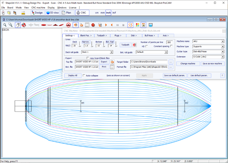
- The "Number of points per line" set the number of points per line in the exported cutting file. The higher the better the precision, but also the longer it takes to compute. Some controllers can't handle a very high number of points per line.
- "HD" will double the precision used during the computation and multiply the computation time by 2 to 10.
- "Constant spacing" will make the points evenly spaced along the length of the board in the toolpath.
- Press "Toolpath"
to compute the toolpath and have it drawn on the screen. This
later function is also present in the tool bar
![]() .
.
- When the cutting path looks satisfying on the screen, choose the name of the cutting files you want to export (name of the file followed by _top and _bot by default) and the folder "Target folder" where you want to export the cutting files.
- "Export" will create the cutting files.
- Press "Print" to see the cutting paper sheet, with the information about the board, the blank, and the machine setting.
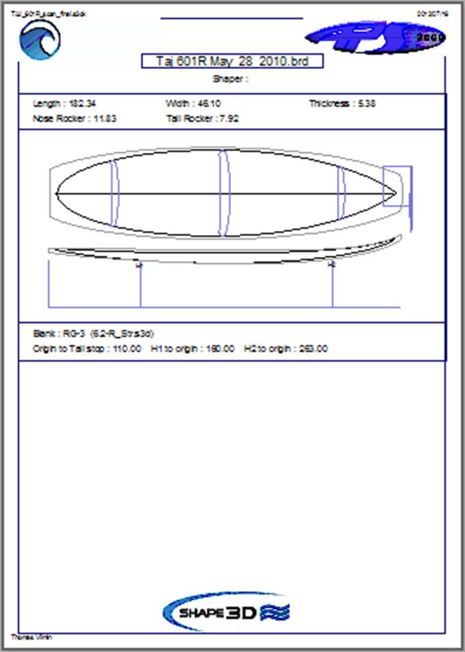
- The button "..." next to the "Format File" field allows browsing to choose the text file used to create the structure of the exported cutting files. You can change the header and the footer of this file to correspond exactly to your machine needs.
Shape3d handles a lot of machine types and configurations.
- "Machine" corresponds to the brand of your machine. If the brand of your machine isn't in the list, choose "Standard".
- "Machine type" gives the choice between:
Clamps, the blank is clamped at each end, and these clamps are used to flip the board
after the deck is cut.
Supports, the blank lays on two supports that have a defined position and height.
Supports Axe corresponds to a blank that lays on two supports
during the deck cut, but is then flipped around a fixed axis to cut
the bottom.
Table, the blank lays on a flat table.
Mold allows cutting the mold of a board in a block on a table machine (This mode is still in test on version 9.1.0.4).
- "Cutter type" gives the choice between
Bull Nose
Disk
Symmetric Bull Nose
4-5 Axis Bull Nose
Multi Bull Nose
4-5 Axis Multi Bull Nose
Disk+Bull Nose
All these settings can be saved in the current machine file, or in a new one that will be used as the machine file afterward.
- "Save as default parameters" save in the current machine file.
- "Use default parameters" allows loading the machine file parameters if the parameters have been modified or loaded from the board file.
- "Change machine file" allows loading another machine file.
- "Save as new machine file" will save the current parameters in a new file that will used for the default parameters.
- "Send my CNC parameters" will send us your machine file, board and blank file, so that we have all the needed elements in case you have any problem.
- Once some parameters have been modified, press "Apply" (this will not save the modifications in the machine file).
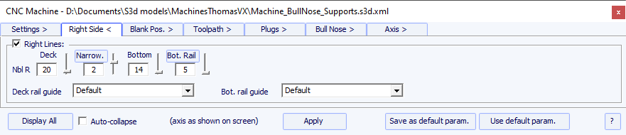
For asymmetric boards, the tab "Right Side" is added, and allows setting a different number of paths on the right and left sides. Note that in this case the toolpath can't be concentric.
- This tab contains the Machine Origin,
which is a very important setting to get precise cuts.
It corresponds to the position of tip of the bottom of the cutter (bull nose or disk) when you run the command X0.0 Y0.0 Z0.0 in your controller.
Note that for the APS3000 and AKU / SurfShaper machine it is not the tip but the center of the front face of the disk!
The coordinates of the Machine Origin can be defined relatively to the tail, nose, or
middle of the blank.
- You can also define here a Flip Offset in case the position of the Machine Origin
won't be the same during the cut of the deck and the cut of the bottom.
![]()
- In this tab you can choose a blank, or use the Auto blank feature with a defined Margin. This is useful if you use an EPS blank made from the profile of the board for example.
![]()
- If the blank is a block of EPS, check the option Block blank and define its dimensions.
![]()
- You can also load a Blank previously designed with Shape3d (or Aku shaper).
![]()
- You can move and rotate the board inside the blank with the mouse or the arrow keys.
You can also set the position of the board in the blank using the Board Position button.
![]()
- The Blank Selector will scan all the blank files from a selected folder and the sub-folders, and display the list of acceptable blanks, with the ones which deck curves best fits the board deck curve on top.
![]()
- Sometimes you'll use one of your blanks but you'll cut a piece of nose and tail because you know it is too long. In this case, instead of re-designing a blank in Shape3d, you can use the Blank tail/nose cut over the length function to say for example that you cut 10cm of the tail and 20cm of the nose.
The use of a blank, even roughly designed, is very important, as it will lead to a cutting path that does not begin right on the clamps, but a bit farther.
- If the blank is much thicker than the board and you have a short tool, you can use the Stringer Roughing function. The toolpath will cut the stringer in an optimized way so that the tool never cut deeper than the Steps dZ. The Final dZ is the thickness of stringer left after roughing, to be cut during the stringer path. You can set multiple paths shifted by the F. dZ settint the # field to a value higher than 1.
- You can also use the Board Roughing function that will do some quick paths where there's a lot of foam to remove,
never cutting deeper than the Steps dZ value. The Final dZ is the thickness of foam left after roughing
The Margin dY allows enlarging the roughing area.
The check box Along OY set roughing paths in the width direction Y.
The check box Follow blank otl. makes the contour of the roughing paths follow the outline of the blank instead of the outline of the board.
The check box Clean surf. adds a path right at the surface of the blank to make sure the dimensions are right.
The check box Outline only limits the roughing to the outline of the board.
There are 3 possible machine settings for the blank holding system.
The blank can be clamped:
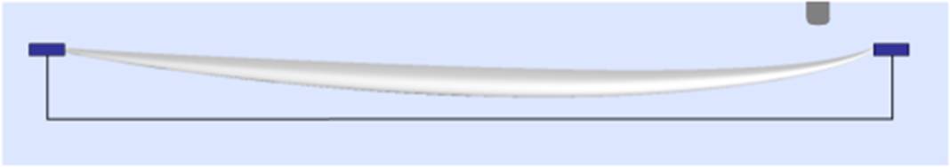
- The center of the Clamps (i.e. the rotation axis) can be aligned either with the upper point, the center point, or the lower point of the extremities of the blank.
- A vertical shift of the clamps between the deck cut and the bottom cut can be set with the box Z level change after upside-down.
- The option Clamp board tips after flip will put the clamps right on the tips of the cut board for the cut of the second side, instead of keeping the clamps on the blank tabs. This option must be used if you do a complete outline cut during the cut of the first side, that removes the tips of the blank.
If you don't use a blank in Shape3d you'll certainly have to shift the whole toolpath up or down with the machine controller (i.e. change the Z of the machine origin) to start the cut right on the deck of the blank. Then don't forget to move the toolpath in the other direction with the controller when you cut the other side:
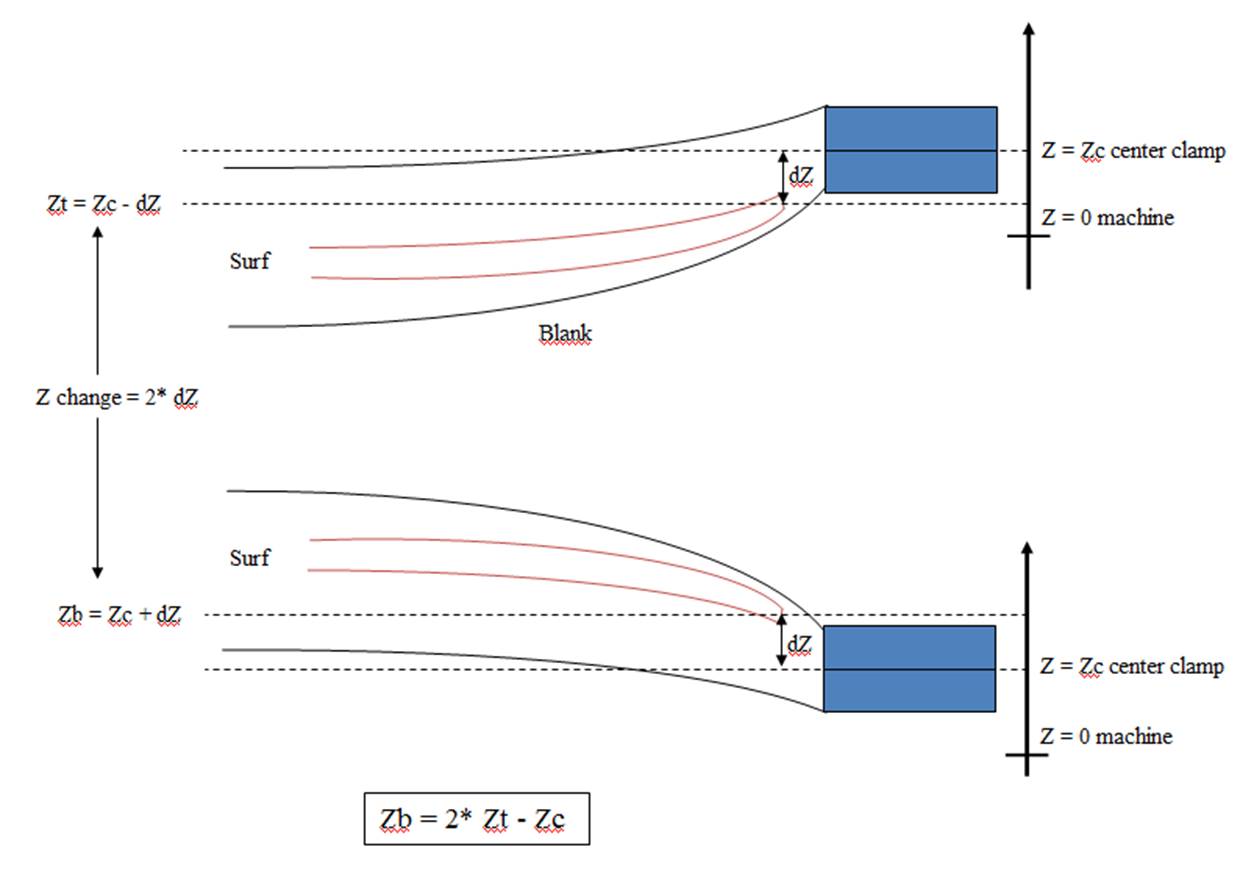
The blank can be supported by two struts:
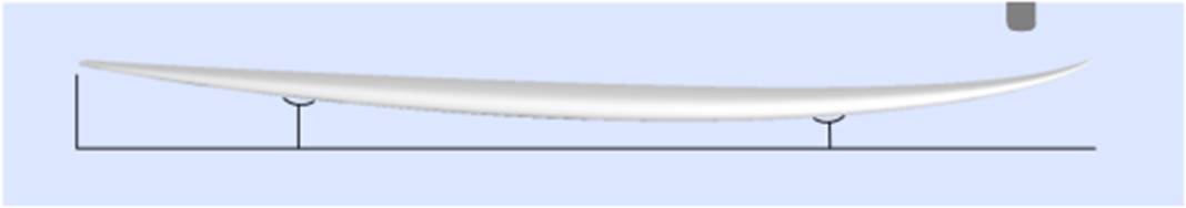
![]()
- In this case the blank can be selected just like in the Clamps mode.
- Set the coordinates of the Machine Origin of the machine relatively to the tail, the nose, the supports or middle of the blank.
- The position of the supports H1 and H2, relatively to the origin of the machine, or the tail or nose of the blank, is set in the section "Supports".
- A vertical shift of the supports between the deck cut and the bottom cut can be set with the box "dZ".
- Note that during the cut of the first side (deck or bottom), the blank is positioned on the two supports. While during the cut of the second side (bottom or deck then), it is the board that is positioned on the supports.
- The Bar supports option sets the supports as horizontal bars instead of 2 contact points per support. This will make a difference as soon as the board has a covex deck or a V.
- A variation of the support mode is the Support Axe mode. In this case, the blank is positionned on the two supports during the cut of the first side. But then the blank is flipped around the horizontal length axis. This mode suits for machines with automatic flip assist system.
The blank can lay on a Table:
- The Table and Mold modes correspond to the CNC machines with a flat bed.
![]()
- In this case the blank lays flat on its lowest point. This mode suits best with Block blank and Rods to hold the board after the cut of both side.
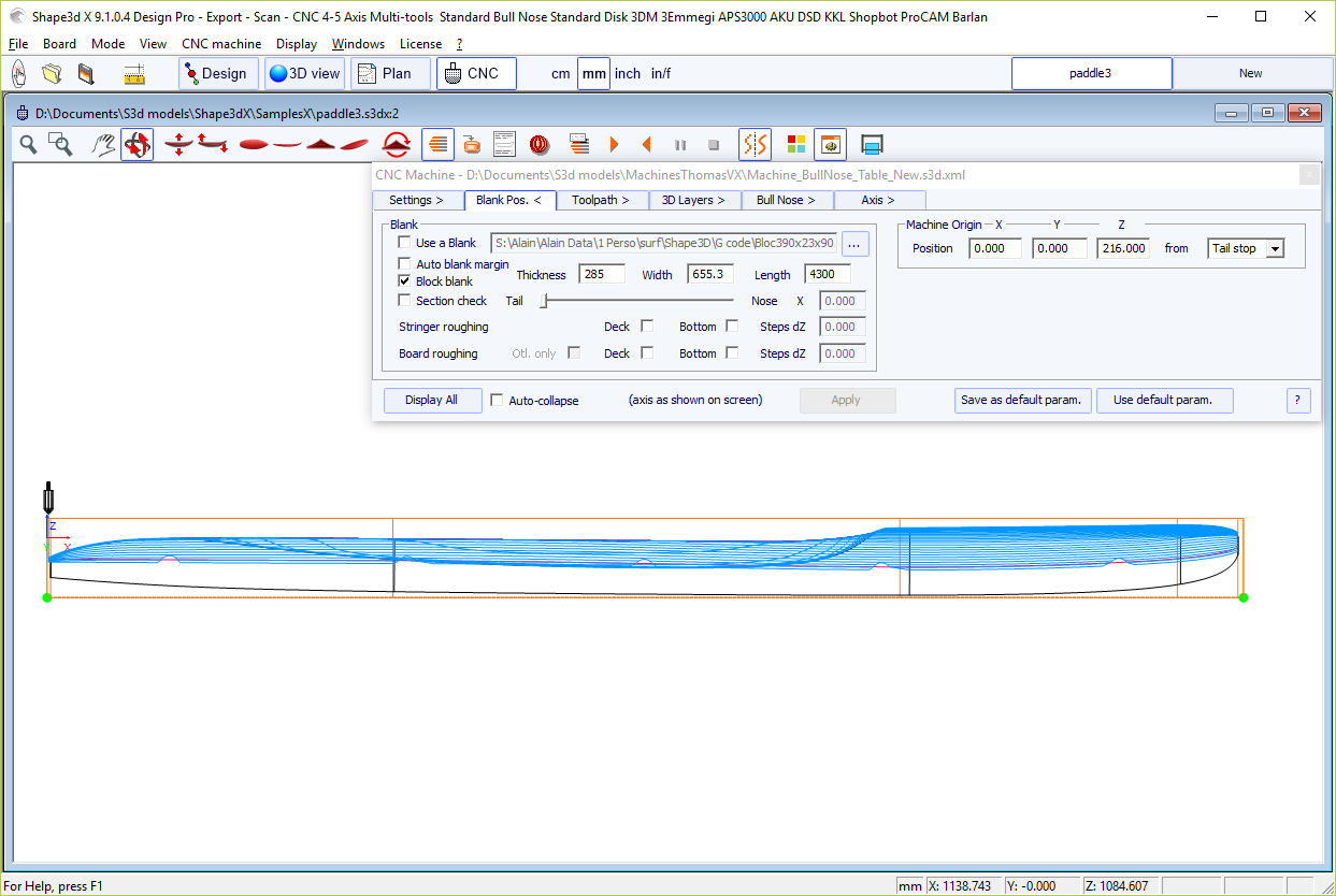
Bull nose
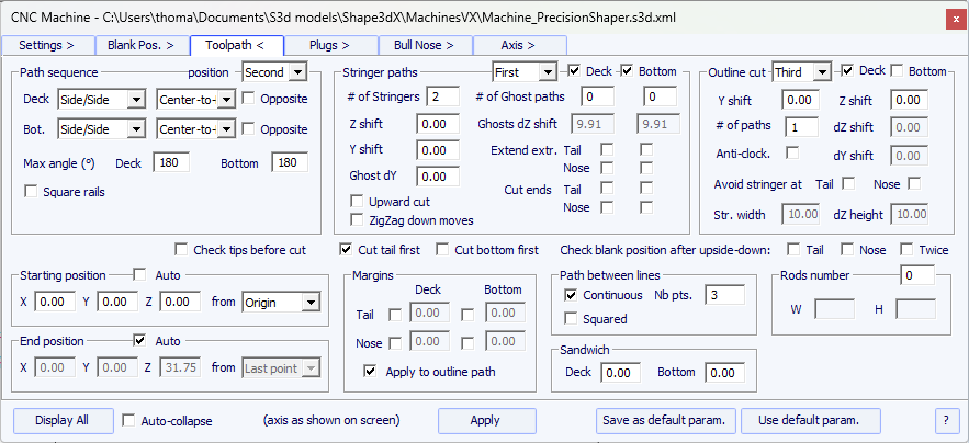
Disk, symmetric bull nose or a 4-5 machine
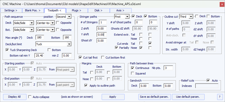
This page defines the general components of the cutting path:
- "Anti-clockwise" will change the rotation direction of the concentric toolpath.
These settings can be different on the deck and the bottom.
- For a 3 axis bull nose you can check the option "Square rail" if you don't want to cut the bottom rail.
For a disk, symmetric bull nose or 4-5 axis, you can choose the separation between deck and bottom cut between the options:
"Apex" sets it at the widest point.
"Tuck" sets it as low
as possible (depending on the dimensions of the motor) between the
apex point and the rail point. Note that if the motor is thick, the
lower lines are intentionally deviated from the original path in
order the motor to avoid the blank.
In this mode, you can use the "Tuck Sharpening" option to avoid blunting
the tuck if the machine is not perfectly aligned.
"Tuck+Flat Bottom" is the same as "Tuck", but the bottom lines are limited to the rail point.
"Square rail" doesn't cut the bottom rail.
"Up rail" sets the separation as low as possible when you cut the bottom.
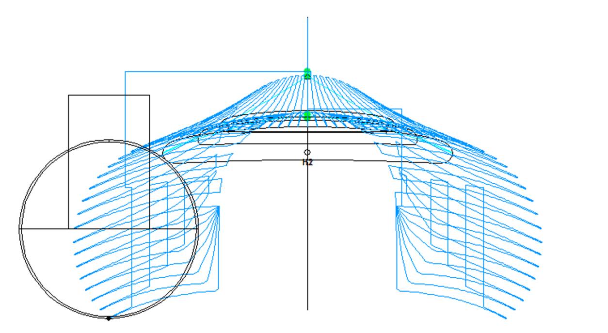
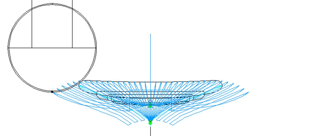
- In both case, you can define a "Maximum angle" so that the toolpath doesn't go too low on the rail:
If you let it to 180° for Deck and Bottom, then it'll cut the bottom rail during the deck cut
as low as possible without the motor hitting the blank.
If you set the Deck Maximum angle to 120° for exemple, it'll stop the bottom rail cut
where the normal of the rail make an angle of 120° with the vertical axis.
Then, if the separation is set to Tuck, the rest of the bottom rail will be cut during the bottom cut.

- The "Bottom rail min Y and Z" field will aslo limit the bottom rail cut during the deck cut so that the disk doesn't go too low or too close to the supports.
- The "Number of Stringers" can be set between 0 and 3. Set 0 if you don't want to cut the stringer of the blank. Set 2 or 3 if the blank has several stringers.
- Then set the "Side shift", which is the distance between the stringers and the center axis.
- The "Z margin" will give a stringer cut higher than the actual stringer if set positive. You can use it if you want to finish the stringer by hand.
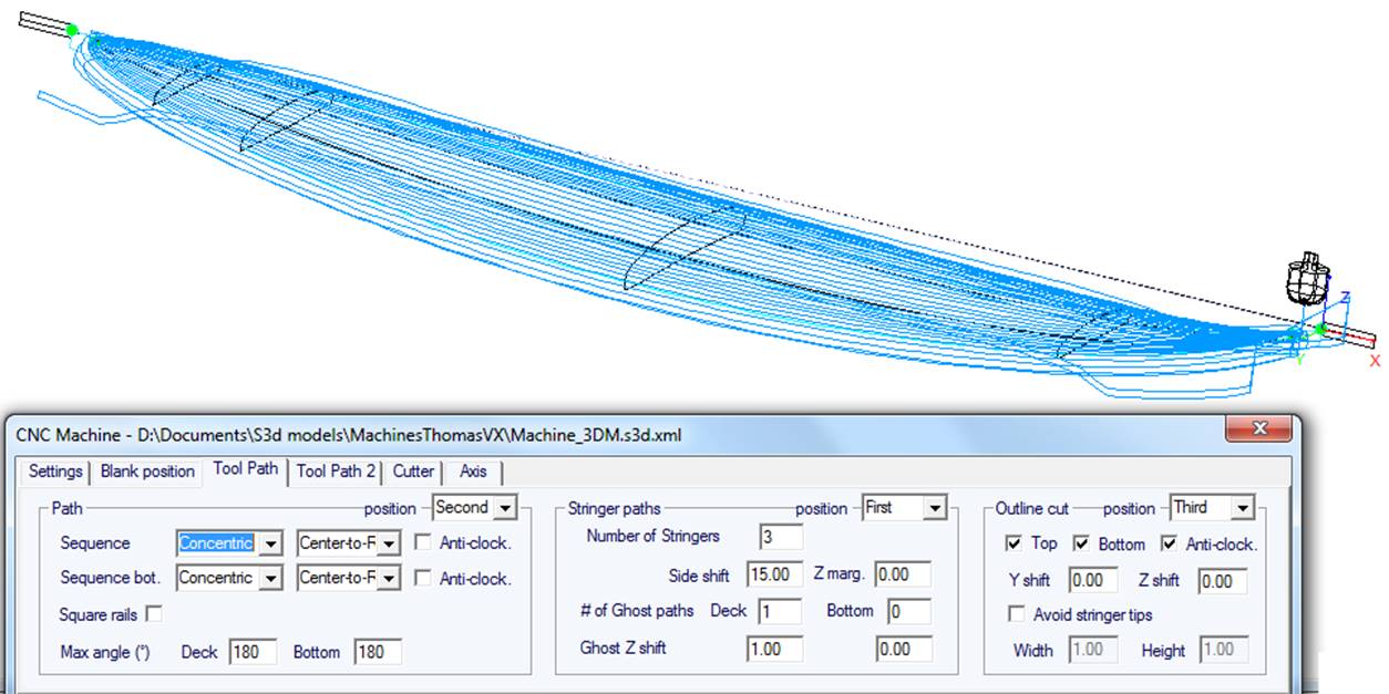
- You can also add one or several Ghost paths with a "Side shift" and a "Z shift" (for several ghost paths the Z shift diminishes step by step).
- For Bull Nose cutter, the option "Upward cut" creates a stringer path that always cut upward, to avoid foam burning.
- Also for Bull Nose cutter, the option "ZigZag down moves" replace all the vertical down moves at the beginning or between stringer paths by ZigZag moves, to avoid foam burning.
- For Disk+Bull Nose machines, the "Swallow tail cut" option allows cutting the swallow tail with the router at the end of the bottom cut, it case it is not already cut as a 3D layer.
- If you check the boxes "Extend stringer", the stringer path will be extended horizontally to finish up the tip.
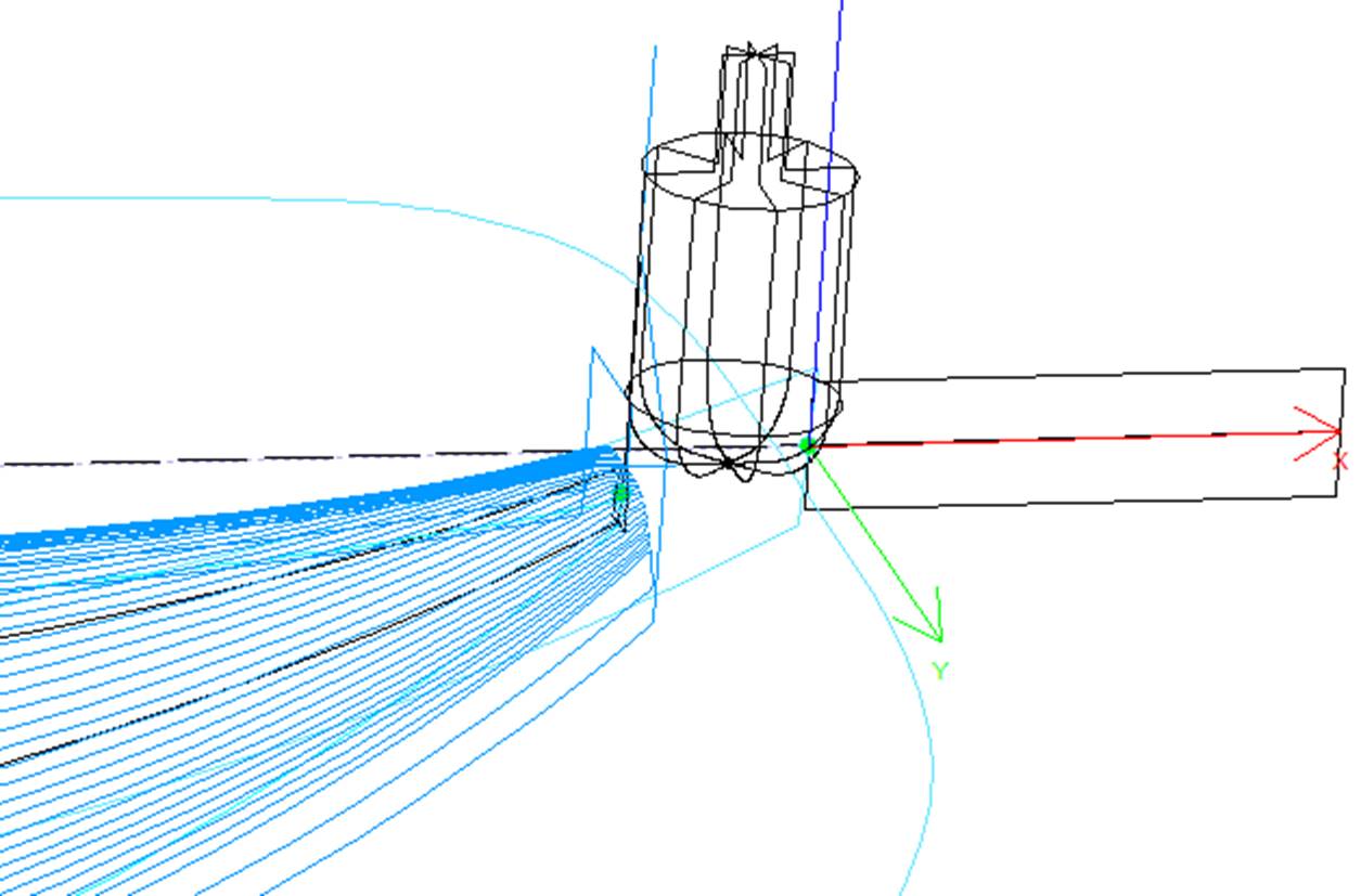
- You can also check the "Cut stringer ends" boxes to make the tool go down at the tip of the stringer to cut the last piece of wood.
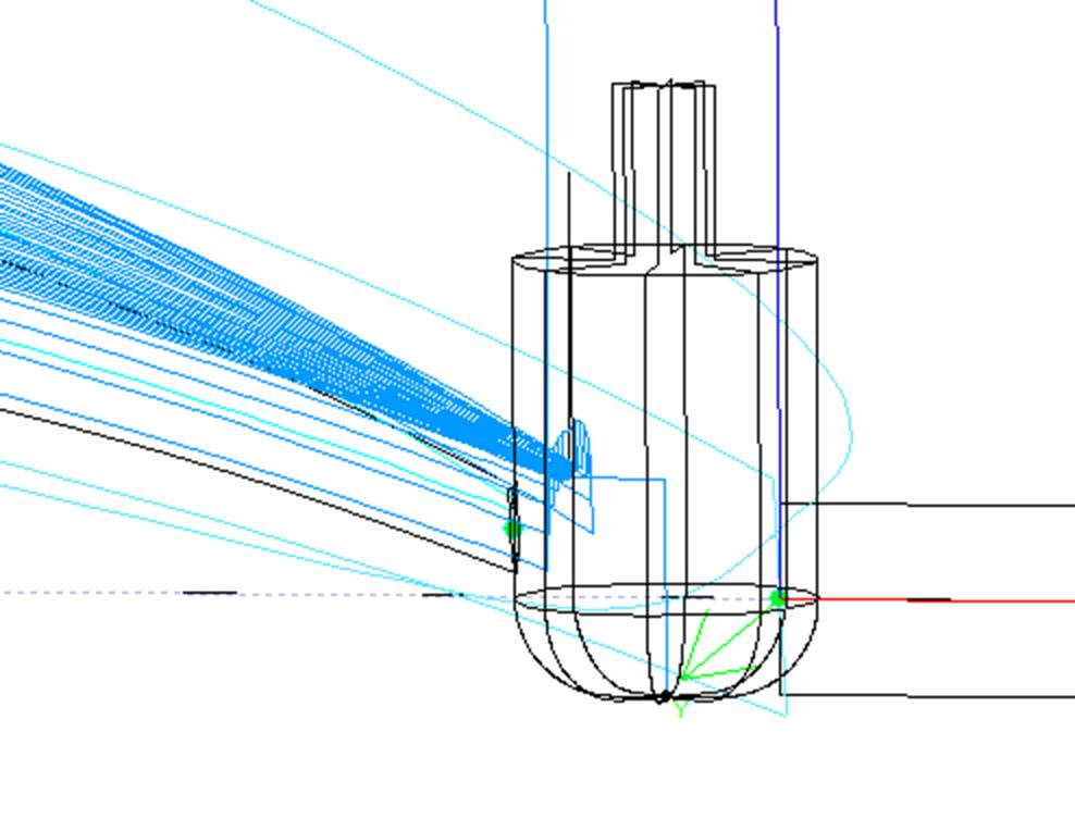
For 3 axis machines with a bull nose cutter one can add an outline path to the deck and/or bottom cut.
The default outline path is computed so that the cutter goes as far down until the bottom of the blank,
but not deeper than the height of the tool.
You can add a "Y shift" so that the outline path leave a little
bit of foam for the hand finish. And a "Z shift" if you want to move
this path upward or downward. These parameters can be different for deck and bottom.
You can set several outline paths with a "dZ shift" and "dY shift" between each path.
You can change the rotation direction checking the "Anti clockwise" box.
Check "Avoid stringer tips" if you want the outline path to hop over the tips of the stringer (and the clamps if clamped). Then you can set the "Str. width" of the stringer (or clamps) and ho height "dZ height".
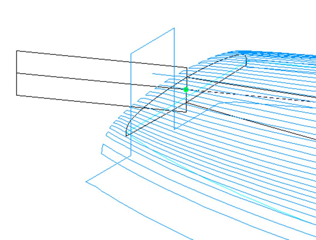
The relative order of these three components can be changed using "Order": stringer path first, then lines, then outline. Or outline path, then lines, then stringer...
The check box "Cut tail first" makes the toolpath start at the tail of the board instead of the nose.
The check box "Cut bottom first" must be used if you start the cut by the bottom of the board instead of the deck.
The check box "Check tips before cut" makes cutter touch the tail and nose tips of the board before the cut si you can check the positionning of the blank.
The options "Check blank position after upside-down" makes the cutter touche each side of the board before cutting the second side of the board to check the alignment.
If the "Starting position" is set to "Auto", the tool path starts 1.25" above the first point of the stringer cut. This can be at the nose, or at the tail if the box "Cut tail first" is checked.
If it's not set to auto, you can set it at any position relatively to the tail, nose, center, origin or first point. Note that tail and nose refer to the top corner of the tail and nose of the blank. While center corresponds to the surface of the final board.
You can define the "End position" of the toolpath the same way.
The "Margins" allow stopping the toolpath before the tips of the boards. They can be set to different values for nose and tail, deck and bottom. It can be used if the board is too long for your machine and you have to cut it in two pieces.
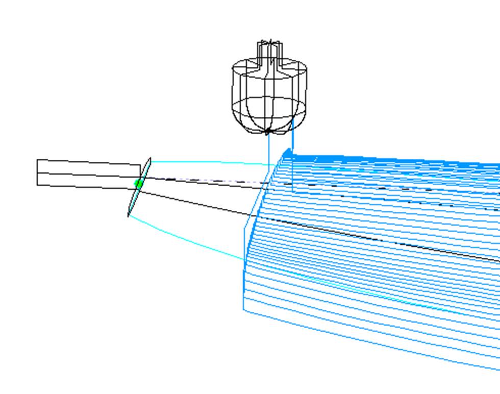
The path between lines, at the tail and at the nose, can be a square move, or a continuous move with a fixed number of positions.
The sandwich field allows removing an additional constant thickness on the deck or the bottom for sandwich construction.
If you cut the board in a block of EPS foam, you may want the board to stay fixed to the rest of the block at the end of the cut instead of falling down. In this case, for bull nose cutters only, you can set a number of rods that won't be cut.
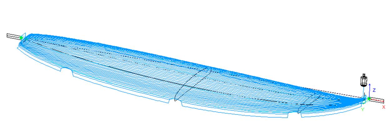
For disk cutters, you can define a number of "Relief cuts" that will remove the extra foam of the blank at the tail so that it doesn't get hit by the motor. You can also check the Auto option so that the number is automatically computer depending on the disk radius and the width of the tail. Or you can define the sequence of relief cuts you want like for example 6-15-22 so there will be a relief cut at the 6th path, the 15th path and the 22th path on each side.
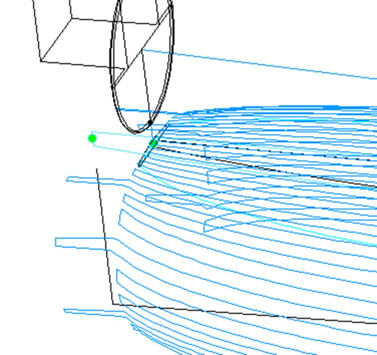
If the board contains Plugs, the CNC parameters window will show a Plugs tab.
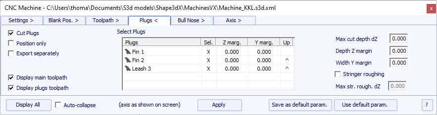
If you check the "Cut Plugs" option, the cutter
dig the holes for all the plugs selected in the plugs list.
The cutting order of the plugs can be changed clicking on the ^ in the Up column.
Note that it will only cut the whole plug if the tool is small enough.
- If the "Position only" option is checked, the cutter will only do a slight mark at the center of the plugs.
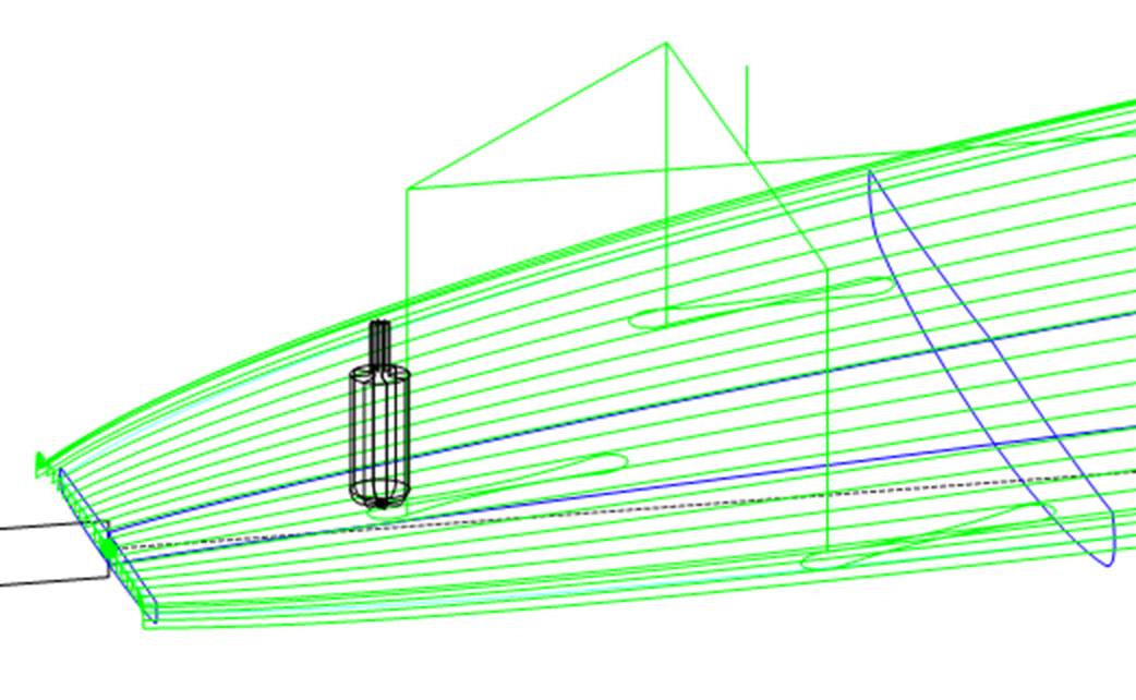
The "Max cut depth dZ" allows cutting the plugs in several steps of depth dZ.
These dZ steps can be set smaller for the center plugs in case there's a wooden stringer using the "Stringer roughing" option.
The plug holes can be done larger or deeper using the "Y and Z margins".
These margins can be defined differently for each plug.
If the board contains 3D layers, the CNC parameters window will show a 3D Layers tab.
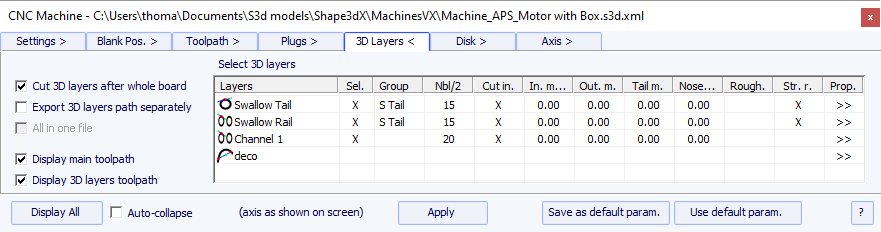
This tab contains the option Cut 3D layers separately that allows cutting the whole deck and bottom without the 3D layers first, and then do a second path to cut the 3D layers. This is very useful for deep recessed deck for example, if your tool is not long enough to cut the whole deck at once. It also gives a better finish since the 3D layers path follows the outline of the 3D layers.
Note that this feature must be used for Concave 3D layers only!
This tab contains the list of the active 3D layers so that you can choose which 3D layer will be cut with the whole board, and which should be cut afterward.
The selected 3D layers will be cut one after the other except if you set the same Group name for several 3D layers. The 3D layers of a same group will be cut in the same path.
The option Export 3D layers path Separately allows to export the whole deck or bottom toolpath in one file, and the 3D layers toolpath in another file. This option is useful if you want to use a different tool for the 3D layers. If you don't have the multi-tools option, you can generate the whole deck toolpath with one cutter, then change the cutter dimensions and re-export the cutting files with a different name.
The option All in one file concerns the case where you cut the 3D layers one after the other and export their paths separately, but you want one file for all the 3D layers and not one per 3D layer.
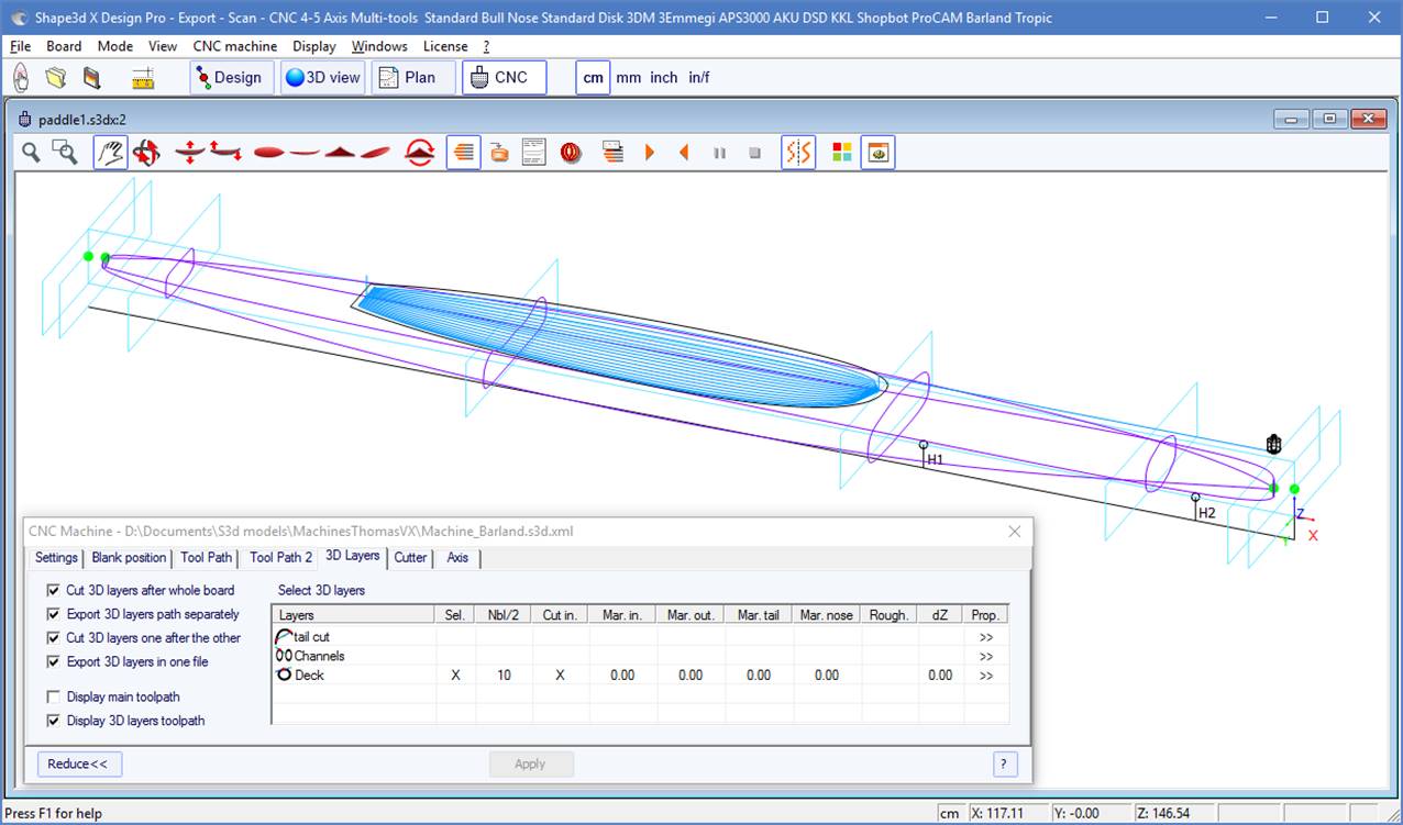
For each 3D layer you can set the number of lines, the margins, and also add roughing paths.
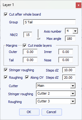
The option Cut inside layers will create a tool path with an outside path shifted by the cutter's radius.
The Group allows to cut several 3D layers at the same time.
You can choose the number of paths on the selected 3D layer.
For 5-4 axis machines, you can choose to limite the cut of a 3D layer to 4 or 3 axis.
You can also set a Margin so that the cut of the 3D layer starts a little inside.
The Roughing adds several paths to limit the depth of each path to a maximum value Steps dZ.
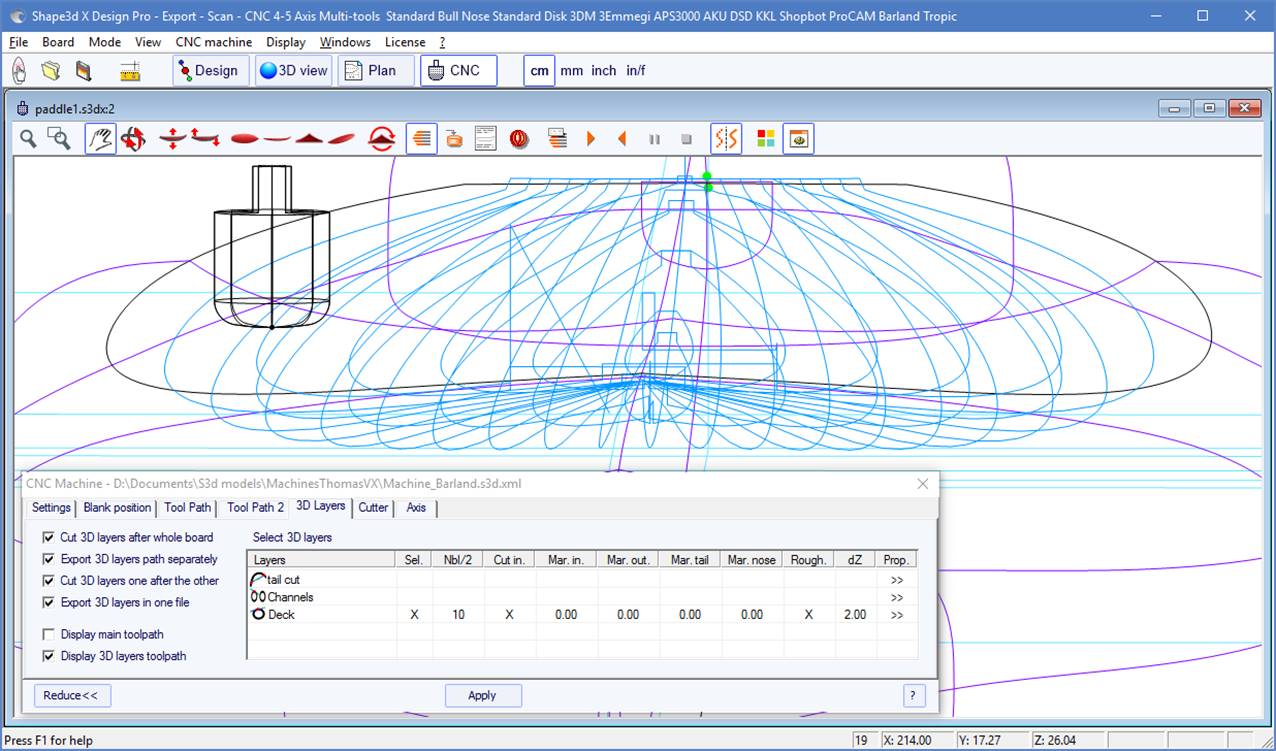
For Multi-tools machines, you can choose a different cutter for the cut, the roughing, and the stringer roughing.
This tab contains the cutter dimensions as shown on the drawing, whether it's a bull nose, a symmetric bull nose, or a disk.
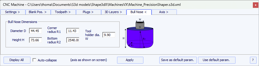
- The Diameter D is the total diameter of the cutter.
- The Corner radius R1 is the radius of the corner of the bull nose. It must be smaller thanb>D/2 (R1 = D/2 gives a spherical tip).
- The Bottom radius R2 is the radius of the spherical bottom part of the cutter. It must be larger than D2. Set R2 to a very high value if the bottom of your cutter is flat. But the toolpath is usually not as smooth if the bottom of the cutter is flat.
- H is the height of the cutter. It is used to computre the height of the outline path, and also with multi-bull noses if the tools don't all have the same length.
- The Tool holder diameter W is used if larger than the cutter diameter D to avoid any collision with teh blank.
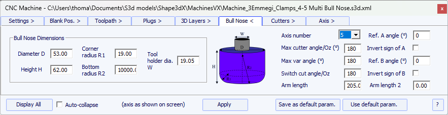
- For 4-5 axis machines, in addition to the cutter dimensions, you can specify the number of axis: 4 or 5.
- The Max cutter angle/Oz is the maximum angle of the tool axis with the vertical axis in Degree (Deg) that the machine can handle.
- The Switch cut angle/Oz is the angle of transition between the cut with the tip of the tool and the cut with the vertical part of the tool. Set this angle between 45 Deg and 90 Deg to cut the bottom rail of the board with the vertical part of the cutter.
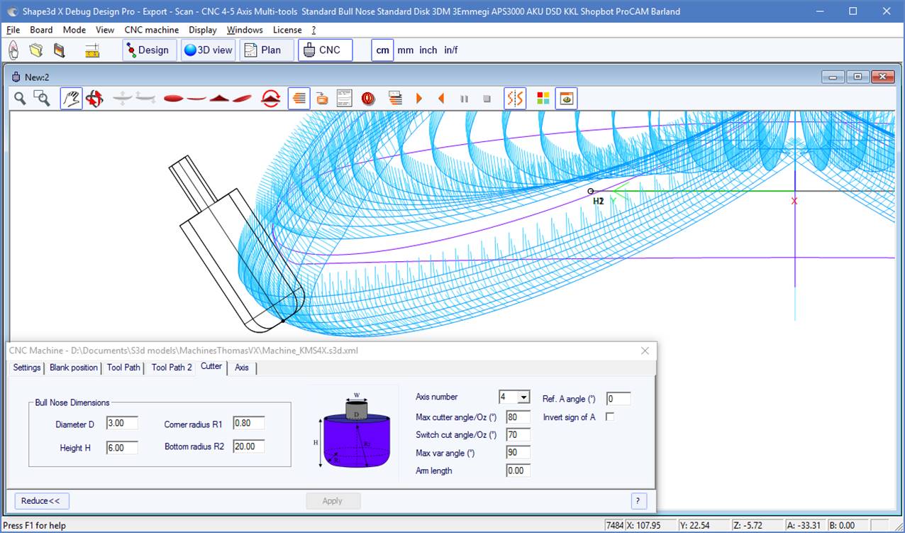
- The Max var angle is maximum variation of the tool angle along one path from tail to nose. If this angle is set to 0, the tool will keep a constant tilt from tail to nose, the tilt changing between each line.
- The Arm length is the length of the arm between the center of rotation to the tip of the tool.
- The Ref. A angle is the angle A written in the exported cutting files when the tool is vertical. The sign of the angle can be inverted.
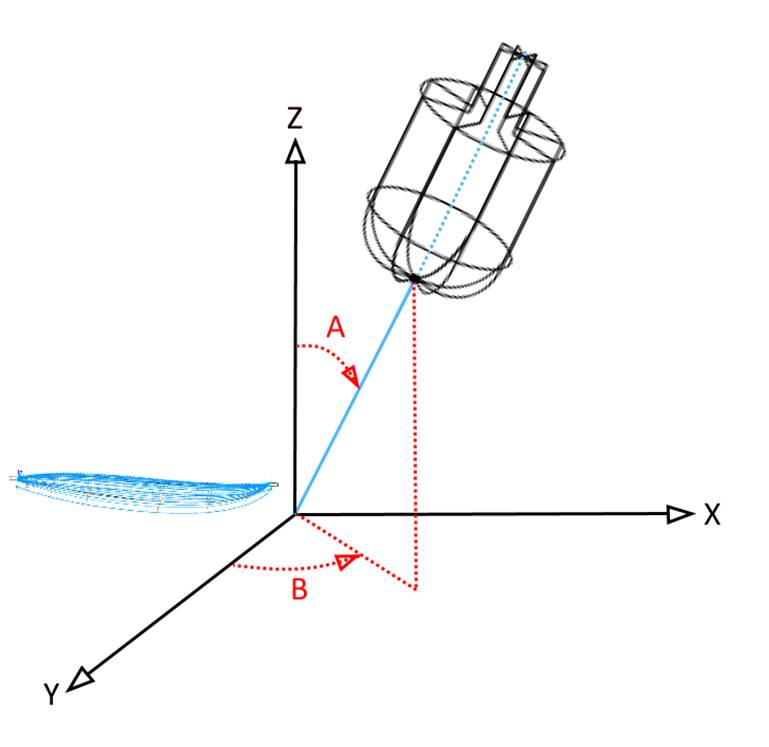
- The Ref. B angle (for 5 axis only) is the angle B written in the exported cutting files when the arm is in the Oyz plan (the slices plan). The sign of the angle can be inverted.
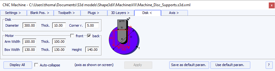
- The Diameter is the total diameter of the disk.
- The Thickness is the thickness of the disk.
- The Corner radius is the radius of the edge of the disk (0 if squared, thick./2 if rounded).
- The disk motor can be placed at the front of the disk (toward the nose of the boards), or at the back (toward the tail of the boards).
- You can define the Width and Thickness of the arm that holds the disk. The arm has a semi-circular bottom.
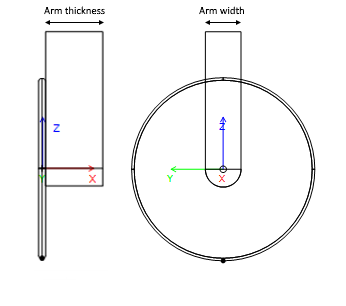
- And you can define the Width, Thickness and Height of the box that contains the disk motor, if larger than the arm.
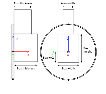
- Arm and motor box dimensions are used to compute the lowest part of the bottom rail that can be cut with the deck without the motor touching the blank.
- On Aku/Surf Shaper machines, you can set the positions of the Acuators.
- On APS3000 machines, you can define the size of the frame of the machine to avoir damaging it with the disk.
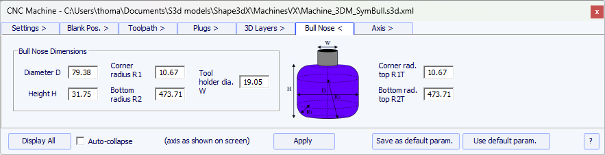
The dimensions of a symmetric bull nose are defined the same way as
for a regular bull nose.
The top radius R1T and R2T can be different than the bottom radius.
The Tool holder diameter W is used to compute the lowest part of the bottom rail that can be cut with the deck without the axis touching the blank.
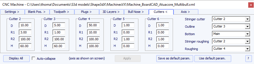
With the multi bull nose option, you can defined the dimensions of
up to 6 cutters: one for the Stringer path, one for the Outline
path, one for the Roughing, one for the 3D Layers, one for the Plugs, one
for the rest of the Bottom cut.
For each cutter you can define an offset relatively to the main cutter.
The option Export cutters paths separately allows exporting the toolpath of each cutter in a different file.
The default command for tool changing are (except for APS3000, Aku/Surfshaper and 3Emmegi):
Start main cutter: <Change to cutter 1>
End main cutter: <U5>
Start cutter 2: <Change to cutter 2>
End cutter 2: <U4>
Start cutter 3: <Change to cutter 3>
End cutter 3: <U3>
Start cutter 4: <Change to cutter 4>
End cutter 4: <U6>
Start cutter 5: <Change to cutter 5>
End cutter 5: <U7>
Start cutter 6: <Change to cutter 6>
End cutter 6: <U8>
These commands can be changed adding the following tags in the post processor format file:
Start main cutter: <START_TOOL_1> ... </START_TOOL_1> <
End main cutter: <END_TOOL_1> ... </END_TOOL_1>
Start cutter 2: <START_TOOL_2> ... </START_TOOL_2>
End cutter 2: <END_TOOL_2> ... </END_TOOL_2>
Start cutter 3: <START_TOOL_3> ... </START_TOOL_3>
End cutter 3: <END_TOOL_3> ... </END_TOOL_3>
Start cutter 4: <START_TOOL_4> ... </START_TOOL_4>
End cutter 4: <END_TOOL_4> ... </END_TOOL_4>
Start cutter 5: <START_TOOL_5> ... </START_TOOL_5>
End cutter 5: <END_TOOL_5> ... </END_TOOL_5>
Start cutter 6: <START_TOOL_6> ... </START_TOOL_6>
End cutter 6: <END_TOOL_6> ... </END_TOOL_6>

The last cutter option is Disk - Bull Nose or Disk - Multi Bull Nose. It allows defining the Disk as main cutter, and then one or several routers to cut special parts like
the plugs, 3D layers, stringer or outline.
The tool change commands work the same way as with the Multi Bull Nose option above.
This page contains the settings of the axis of the CNC machine.
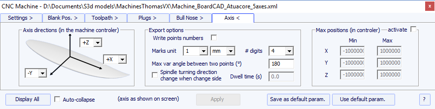
Set the X, Y and Z axis and their directions as in your machine, relatively to the blank.
You can change the unit used in the exported files independently to the unit used in Shape3d. You can also change the precision of the positions written in the files.
For 4-5 axis machines, you can set the "Maximum angle changecbetween two following positions" in degrees. For example if you set it to 5°, when the cutter tip is supposed to stay at the same point but the angle of the arm change by 40°, it will put 8 points in the g-code doing an arc.
Check "Write points numbers" if you want a sequential number a the beginning of each line in the file.
The Spindle turning direction change when change side option insert the command line G4 M3 or G4 M4 when the tool goes from the left side to the right side or the other way. You can set a Dwell time to leave enough time for the disk to stop spinning before starting cutting again.
You can fix the Limit positions that your machine can reach.

The four firstbuttonsare identical as in the 3D View:
![]() Zoom in and out,
Zoom in and out, ![]() window zoom,
window zoom, ![]() move, and
move, and ![]() rotate.
rotate.
Then we have specific buttons:
![]() Move the board
Move the board
Click on the surf and move the cursor to move the surf inside the blank.
![]() Rock the board
Rock the board
Click somewhere and move the cursor vertically to rock the board around its tail.
![]()
![]()
![]()
![]() Change the point of view
Change the point of view
![]() Upside down
Upside down
Turn the board and the blank upside down to see the cut of the other side.
![]() Cutting lines
Cutting lines
Display the cutting lines. Right-click on the lines to check the position of the cutter on each point, and move it with the arrow keys.
![]() Export cutting file
Export cutting file
Generate and store the cutting file in the selected directory.
![]() Machine Sheet
Machine Sheet
Show the cutting paper sheet, with the information about the board, the blank, and the machine setting.
![]() Cutting Speed
Cutting Speed
You can change the speed of the cutter at special points of the cutting path (the "cutting points"). Click on this button to display the Cutting Speed window and change the different speeds, or the speed unit.
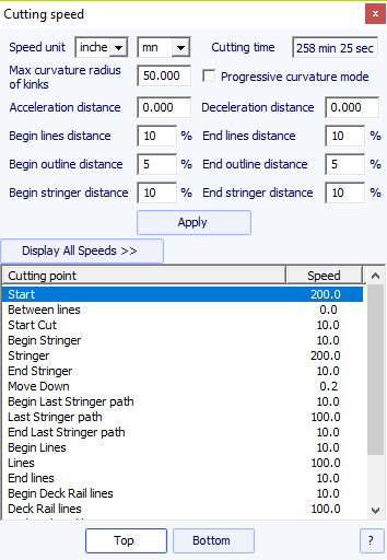
- The Acceleration distance allows for smooth speed increases over this fixed distance. The Deceleration distance allows for smooth speed reductions over this fixed distance.
- You can set a Maximum curvature radius that will define the "kinks" of the toolpath. Then, you can set a special speed for the kink zones. This is especially useful for the wings...
- The Progressive curvature mode lowers the speed proportionaly to the curvature of the path.
- The relative length of the Begin and End areas of the paths can be defined separately for lines, outline, and stringer.
- Click on a line of the Cutting Speed window, to enlighten the corresponding sections of the cutting path. These sections appear in blue when the speed is minimum and red when the speed is maximum.
Double click on the cutting speed window lines to change the speeds.
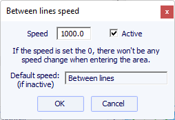
If the speed is set to 0, it means that there won't be any speed change while entering in this speed area.
Each speed section can be de-activated for simplicity, so the Default speed will be applied and less speed will need to be defined.
You can also place the mouse pointer on the cutting path points to display the current speed and right-click on it to enlighten all the cutting path sections that have the same speed. And you can move the cutter along the cutting lines with the up and down arrow keys. Press Enter to show the Cutting Point dialog box and change the value of the speed.
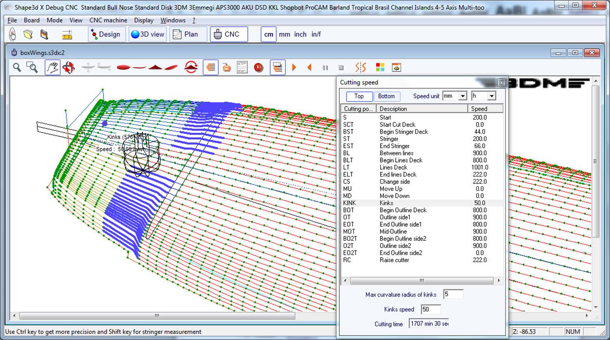
![]() Simulation
Simulation
This feature shows the moving of the cutter in real time (but without taking account of the speed changes)
![]() Finish Solid View
Finish Solid View
This button opens a solid 3D view with an approximation of the result of the cut.
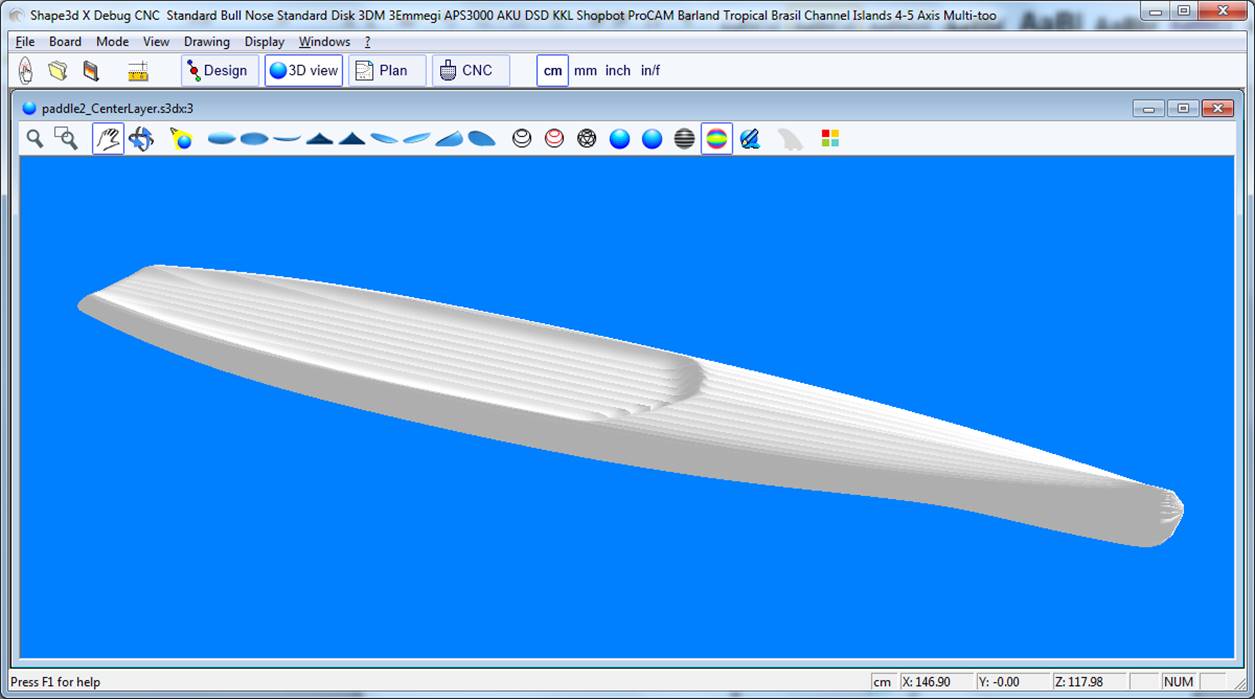
![]() Colors box
Colors box
Allows changing the background colors and the board and blank colors.
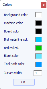
![]() Hot Wire-2D CNC
Hot Wire-2D CNC
The Hot Wire-2D CNC window allows creating and exporting toolpaths for hot wire machines or wood cut machines.
Read more in the chapter Hot Wire-2D CNC.
Most of the options presented in the Menu are also accessible in the toolbar.

It also allows saving the CNC parameters or load new ones from a Machine file.
You can also load the CNC parameters from the board file if it contains some.
You can open the "Cutting speed" window, and start a cutting simulation.
You can display the "3D cutting finish" view.
The CNC properties window can be opened from the Windows menu.

Center view (Escape key) allows reseting the board at the center of the screen.
The Scan Import window is accessible from the menu File/Scan import... The "Scan import" facility of Shape3d is a powerful tool that allows one to build a Shape3d model from scan data. It is the best way to design the exact replica of an existing board. Note that the Scan Import window needs the Import option to be used.
- Choose the importation format "BOARD" and browse to open the file you want to import (DXF, G-Code, or text format). Click on the
button "load".
If the data are not already aligned with the axis, check the option "Auto-align Axis". Not that the result is not always good,
depending on the quantity of data and its cleanliness.
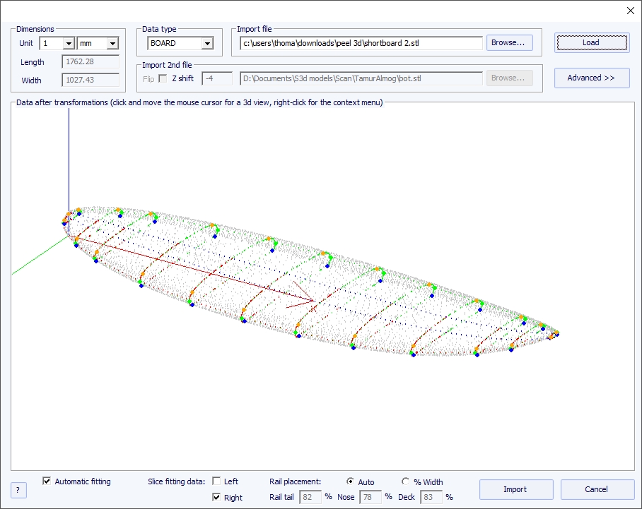
Then you'll be able to import the scan with automatic fitting of the design curves to the extracted scan data.
A key point to get a clean result is the positionning of a control point on the tuck of the bottom rail of the slices, and also on the deck rail.
This is done automatically when the Auto check box is selected. If it's not satisfying you can check the "% Width" option
that will allow you to set manually the position for the bottom rail and deck rail points as a percentage of the width.
Once the rail points are well placed, you can choose to use only the left side or the right side for the automatic fitting.
It gives better results then using both sides when the original board is not perfectly symetrical.
Then check the "automatic fitting" box and click on OK.
It will take a few seconds to adjust the curves on the scan points.
If the scan data doesn't look good on the controller after importation, click on "Advanced":
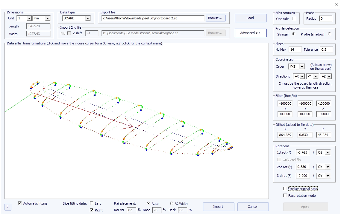
- Check the box "One side" if the file contains only half of the board.
- If the digital probe is a ball, you can input the probe radius, which will be subtracted to the dimensions.
- If you want to import your data into a board that is in the "Stringer" design mode, check Profile detection: "Stringer". The software will then look for the stringer data around the X axis (with the tolerance fixed in the box Slices: "Tolerance"). On the other hand, if you want to import your data in a board that is in the design mode "Profile", check Profile, and the software will look for the lowest and highest points of each slice to create the profile.
- You can also reduce the number of slices if too many of them have been scanned.
- You can tune the tolerance. It allows the importation of slices even if they are not right in the Oyz plan.
- You can switch the axis and change the direction of each axis: the X must be the length direction (towards the nose), the Y must be the width direction, and the Z must be the vertical direction (towards the deck).
- You can reduce the scan data to a window in each direction using the function "Filter".
- You can apply an offset to the data in each direction using the function "Offset".
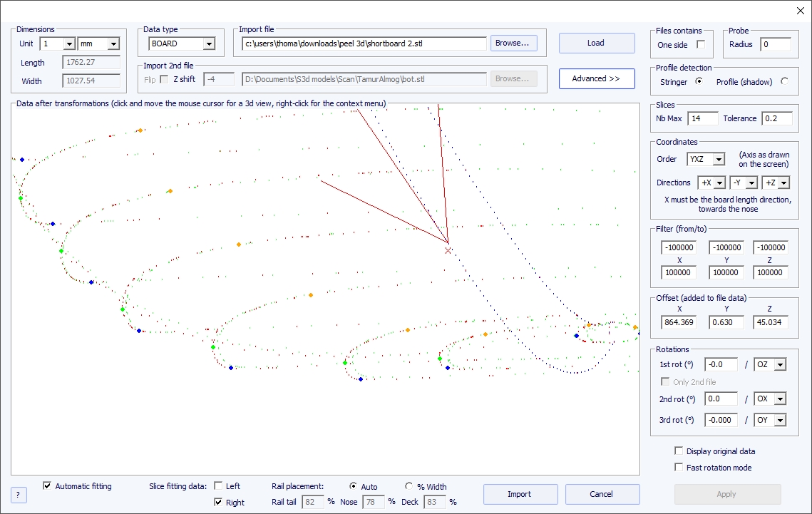
- If the board is not well aligned with the axis, you can apply 3 rotations around the axis of your choice.
Then press "Apply". Note that if you press the button "Load" again, your axis settings will be conserved, but the data will be repositioned so that the tail is at x = 0.
Launch the automatic fitting when it looks good.
You can do the importation of the data without adjusting the curves automatically. Then the dimensions of the model will be adjusted with the data dimensions, but the curves of the model won't be fitted on the guidelines. It can be a good way to see what's wrong with them, and move, or remove, the bad ones.
Then, you can choose to adjust each curve automatically or by hand.
- Choose the importation format "Brd 2files" and browse to open the two files you want to import (DXF, G-Code, or text format). Click on the button "load".
- Check the box "Flip" if the second file (containing the top or the bottom data) is flipped compared with the first one. Then you can shift it vertically using the box "Z shift".
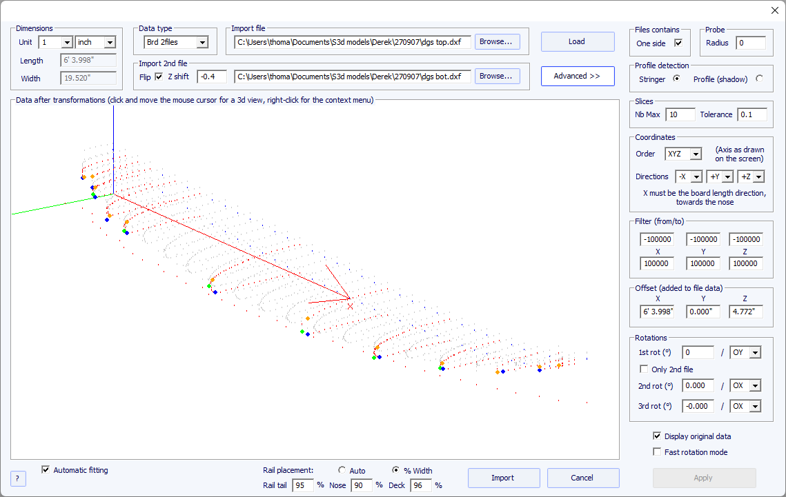
- If the two files don't have the same orientation, you can rotate one relatively to the other. To proceed, press Advanced, and check the box "Only 2nd file". Then set the "1st rot" angle (in degrees) and choose the rotation axis (OY in general).
- Then press Apply or Load.
-All the other commends are identical as for the data type "BOARD".
- Choose the importation format "3DM" and browse to open the .CSV or .txt file you want to import. Click on the button "load". If the file has not been created with the 3DM digital probe it won't be accepted. Then, select the data type "BOARD".
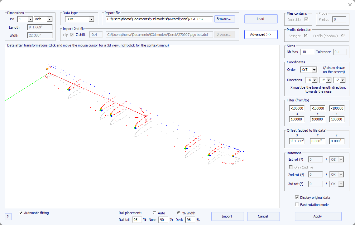
- The rest of the procedure is identical as with the "BOARD" data type.
- The KKL data type corresponds to a .PIM file that comes from the KKL scanning machine. Before loading your file, press Advanced, and make sure the radius of your Probe is set correctly.
- Then set the Tolerance: it corresponds to the shift between the center of the board and the Y position at which the probe begins to scan.
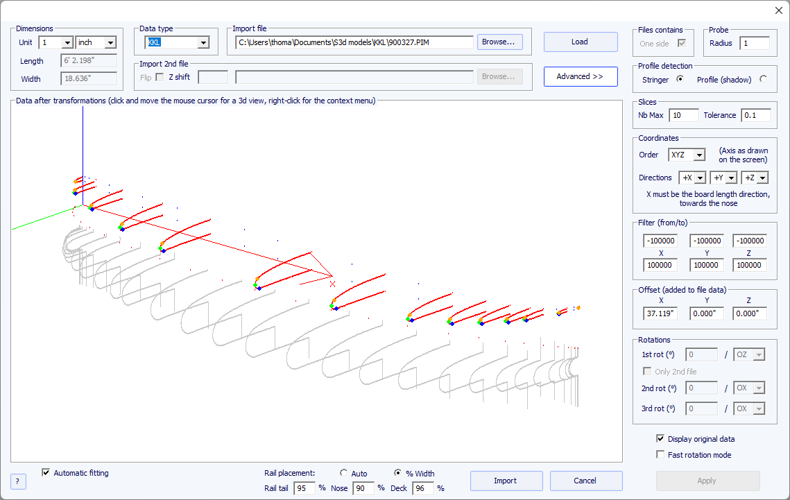
- The rest of the procedure is identical as with the "BOARD" data type.
- These five data types allow importing data to associate guidelines to a particular part of a board.
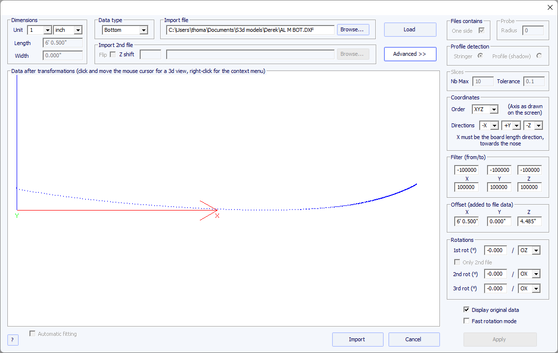
- The data of the types Outline, Bottom, Deck or Thickness will be directly imported into the corresponding curve of the board, while the data of the type Slice will be imported to the selected slice of the board that has already been opened.
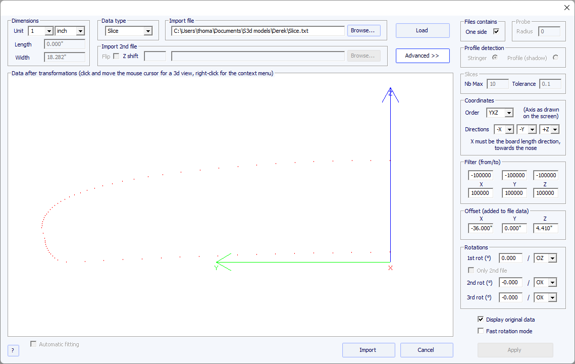
- The fitting of the curves to the imported guidelines must be done automatically, or by hand, after the importation.